Power transmission mechanism capable of preventing breakage of a rotating shaft

a technology of transmission mechanism and rotating shaft, which is applied in the direction of gearing, piston pumps, hoisting equipment, etc., to achieve the effects of preventing the breakage of the rotating shaft, preventing an excess tensile force, and reducing the number of components

Inactive Publication Date: 2007-12-04
DENSO CORP
View PDF11 Cites 4 Cited by
  • Summary
  • Abstract
  • Description
  • Claims
  • Application Information

AI Technical Summary

Benefits of technology

[0008]The above-mentioned problems being taken into account, an object of the present invention is to provide an improved power transmission mechanism capable of: preventing breakage of a rotating shaft from occurring, which might occur in the worst-case scenario; and transmitting without fail a greater torque than before from a rotating body such as a hub to the rotating shaft by: preventing a slip that occurs on the bearing surface consisting of the end surface of the rotating body such as, in general, a hub, and the end surface of a sleeve that comes into contact therewith or a part on the rotating shaft side, corresponding to the sleeve; and by preventing an excess tensile force from acting on the root of a male screw of the rotating shaft.
[0010]As the power transmission mechanism of the present invention has the above-mentioned configuration characteristics, it is possible to increase the value of the equivalent diameter of the part in frictional contact between the bearing surfaces of the rotating body side and the rotating shaft side without the need to increase the size of the power transmission mechanism. As the equivalent diameter is increased, the friction torque is also increased in proportion thereto. Because of this, a slip is more unlikely to occur between the bearing surfaces and an excess tensile force can be prevented from acting on the root part of the male screw of the rotating shaft and, therefore, it becomes possible to prevent the worst-case breakage of the rotating shaft and to transmit without fail a greater torque than before between the rotating body and the rotating shaft.
[0011]According to the present invention, as an end surface is formed as a bearing surface on the rotating shaft side, it is possible, as in the prior art, to easily manufacture a power transmission mechanism having the characteristics of the present invention by attaching a sleeve, which is provided separately, to the rotating shaft having a relatively small diameter by mean of, for example, insertion under pressure.

Problems solved by technology

However, each of these methods brings about a problem.

Method used


Image

  • Power transmission mechanism capable of preventing breakage of a rotating shaft
  • Power transmission mechanism capable of preventing breakage of a rotating shaft
  • Power transmission mechanism capable of preventing breakage of a rotating shaft

Examples


Embodiment Construction

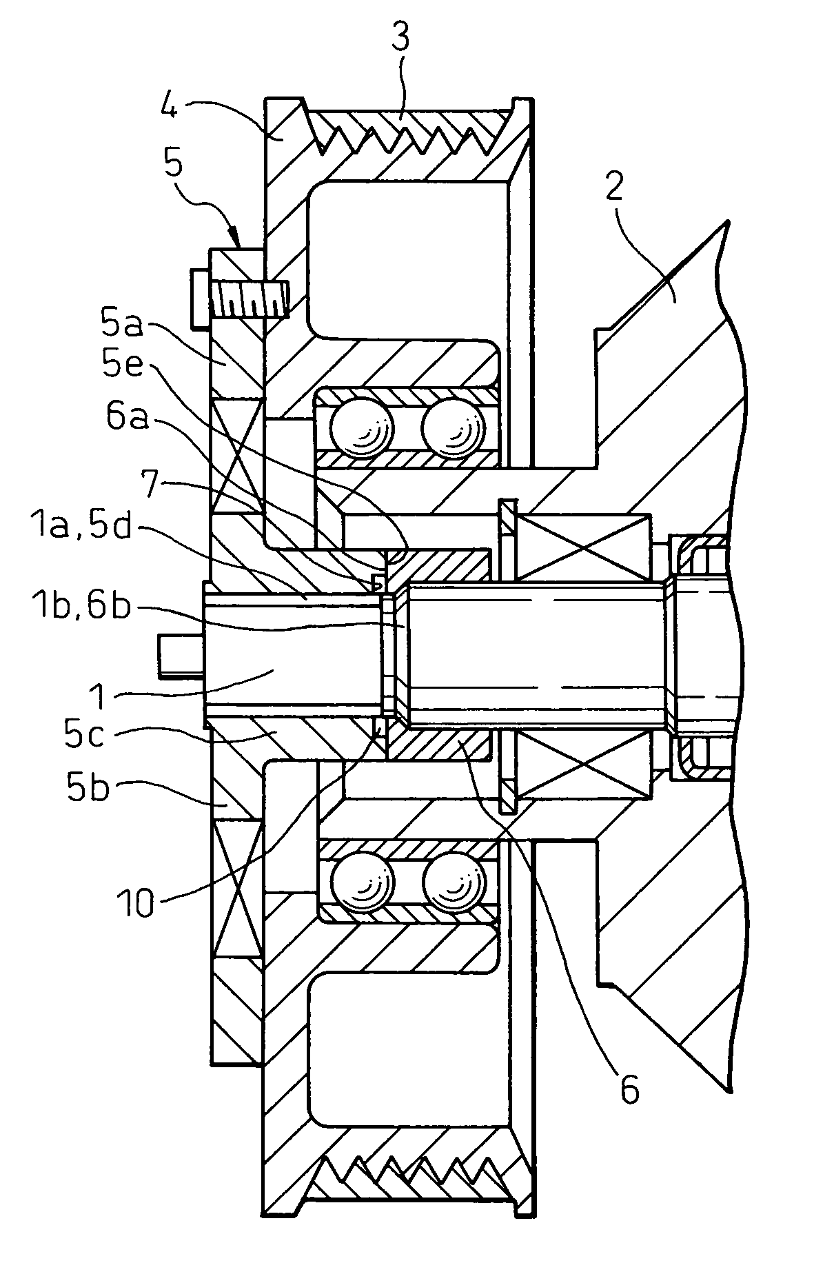
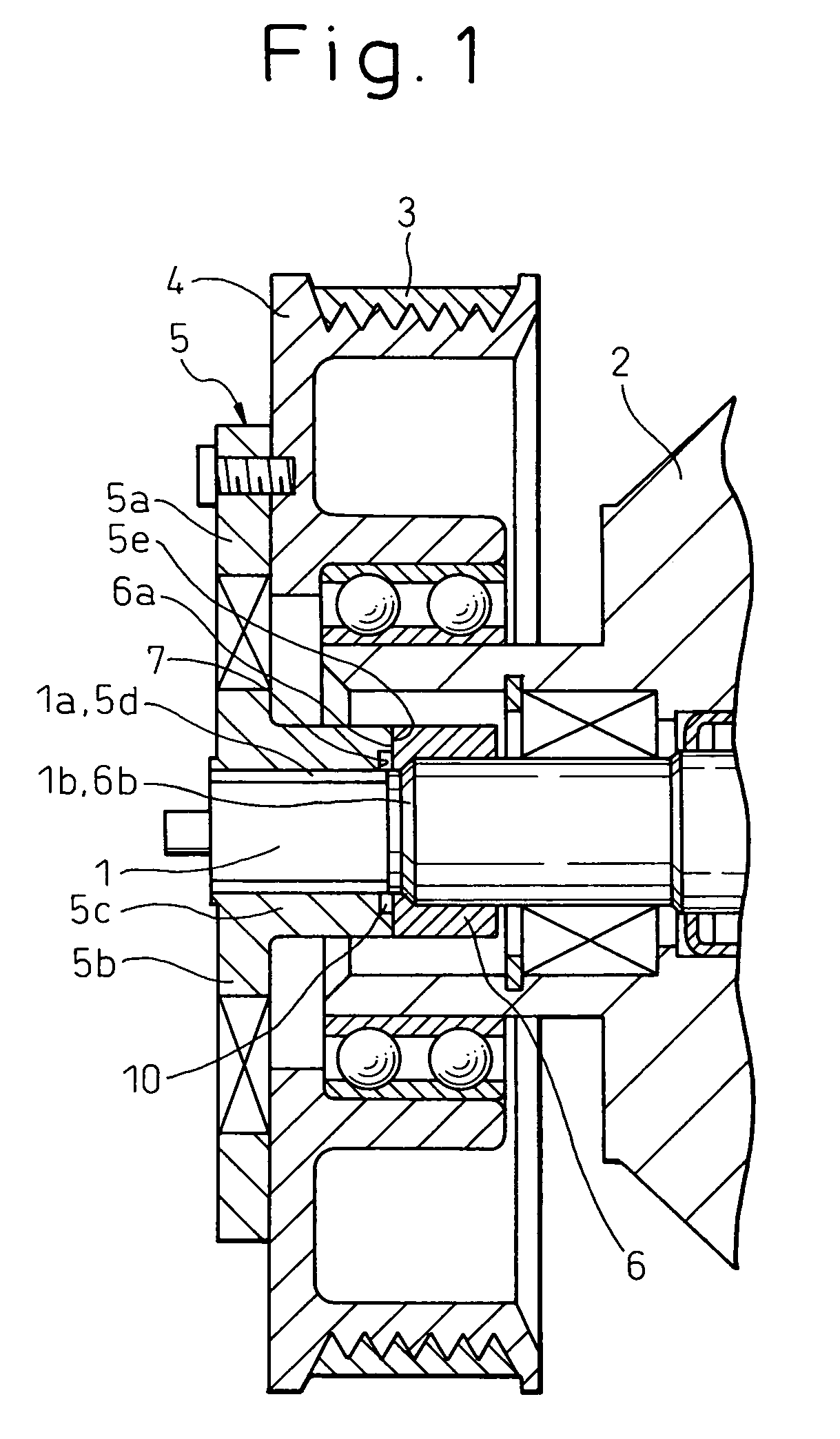
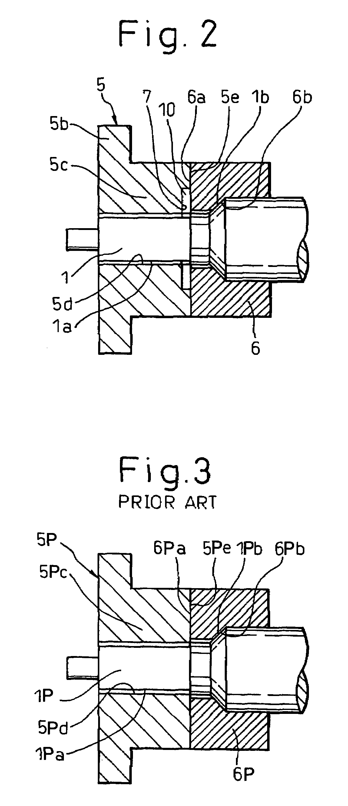
[0021]A first embodiment of the present invention is explained below with reference to FIG. 1 and FIG. 2. FIG. 1 shows the general configuration common to the above-mentioned prior art and FIG. 2 is an enlarged view of only characteristic parts (important parts) in the first embodiment of the present invention. Concerning the details of the parts, shown in FIG. 1, that are common to the prior art, the explanation of the prior art described above also applies here.

[0022]In FIG. 1 and FIG. 2, reference numeral 1 denotes the rotating shaft of the refrigerant compressor 2, 1a denotes a male screw formed on the end part of the rotating shaft 1, and 1b denotes a tapered surface formed on a part of the rotating shaft 1. Reference numeral 3 denotes a belt that transmits a torque from, for example, a vehicle engine (not shown) to a pulley 4. Reference numeral 5 denotes a hub (in general, a rotating body) attached to the pulley 4 with bolts, or the like. An outer part 5a and an inner part 5b ...


PUM


Abstract

In order to transmit a torque from a hub 5 (rotating body) integrally formed together with a pulley 4 to, for example, a sleeve 6 inserted under pressure into a rotating shaft 1 of a refrigerant compressor 2, end surfaces 5e and 6a, which act as a bearing surface, are brought into frictional contact with each other. An axial pressing force is generated by the engagement of screws 1a and 5d of the rotating shaft 1 and the hub 5. An annular cut-out part 7, etc., is provided to form an annular space 10 in a part of the bearing surface around the rotating shaft 1. Thereby, the equivalent diameter of the bearing surface is increased, a slip is more unlikely to occur on the bearing surface, and it is therefore no longer necessary to apply an excessive pressing force to obtain a large friction torque.

Description

BACKGROUND OF THE INVENTION[0001]1. Field of the Invention[0002]The present invention relates to a power transmission mechanism provided in order to absorb, buffer, or cut off an excessive torque when the torque is transmitted. More particularly, the present invention relates to a power transmission mechanism suitably used as a part that transmits torque from a pulley to the rotating shaft of a refrigerant compressor in a belt transmission device for rotatably driving a refrigerant compressor of an air conditioner for a vehicle.[0003]2. Description of the Related Art[0004]A prior art reference relating to this type of power transmission mechanism is Japanese Unexamined Patent Publication (Kokai) No. 2003-35255 (JP 2003-35255). Important parts of a power transmission mechanism described in (JP 2003-35255) are shown in FIG. 3. There may be a case where the general configuration except the important parts is similar to that according to the prior art described in (JP 2003-35255), when ...

Claims


Application Information

Patent Timeline
Patent Type & Authority Patents(United States)
IPC IPC(8): F16D7/02F04D29/043F04B9/02F04B35/00F16D1/06F16D9/00F16D43/21F16H55/36
CPCF16D7/025F16D43/215Y10T403/7092
Inventor NAKASHIMA, MASAFUMI
Owner DENSO CORP
Why Eureka
Try Eureka