Cooking device

A technology for cookers and heating chambers, applied to electric heating fuel, lighting and heating equipment, household heating, etc., can solve problems such as microwave difficulties, achieve the effects of reducing pollution, reducing danger, and improving safety

Inactive Publication Date: 2013-05-08
SHARP KK
View PDF6 Cites 10 Cited by
  • Summary
  • Abstract
  • Description
  • Claims
  • Application Information

AI Technical Summary

Problems solved by technology

[0012] As mentioned above, it is very difficult to simultaneously prevent the outflow of condensed water and reduce the leakage of microwaves

Method used


Image

  • Cooking device
  • Cooking device
  • Cooking device

Examples


Embodiment Construction

[0044] Hereinafter, the heating cooker of the present invention will be specifically described with reference to illustrated embodiments.

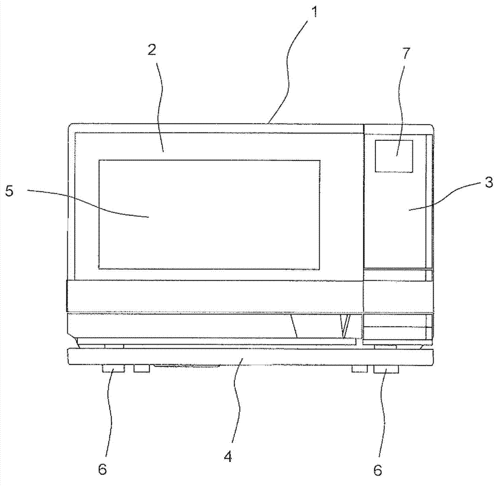
[0045] figure 1 It is a front view of the heating cooker which concerns on one Embodiment of this invention.

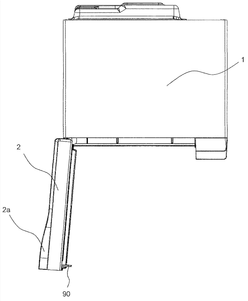
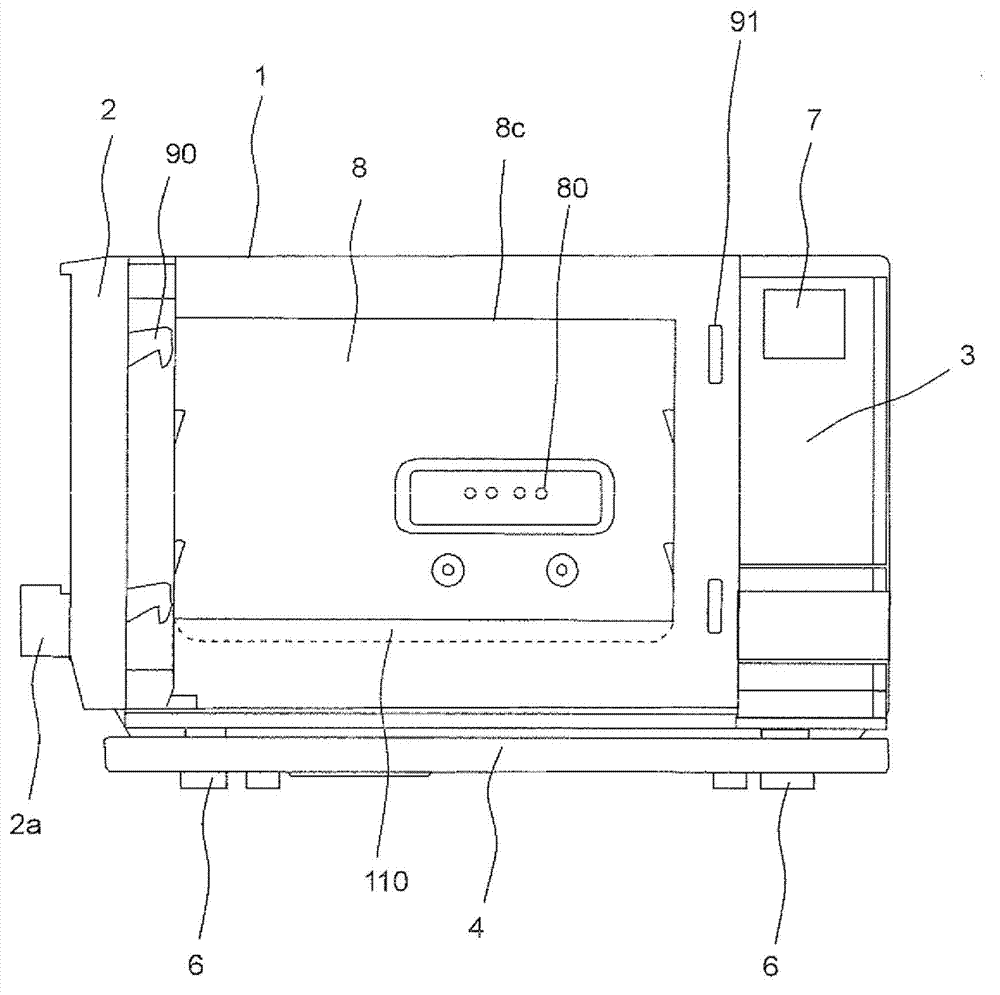
[0046]The heating cooker includes a casing 1 and a handle-equipped door 2 which is an example of a door attached to the front side of the casing 1 . A heat-resistant glass 5 is installed substantially in the center of the handle-equipped door 2 . Furthermore, an operation panel 3 is provided on the front surface side of the housing 1 adjacent to the handle-equipped door 2 when it is closed. Moreover, the dew receiving container 4 is arrange|positioned below the handle-equipped door 2 and the operation panel 3. As shown in FIG.

[0047] The operation panel 3 has a liquid crystal display unit 7 for displaying according to an operation. In addition, although not shown, the operation panel 3 is provided with a plurality of button...


PUM


Abstract

A cooking device is provided with a heating chamber (8) which is provided within a casing, has an opening (8c) on the front surface side thereof, and contains an object to be heated. A dam section (110) extending above the bottom surface inside the heating chamber (8) is provided at the lower edge of the opening (8c) of the heating chamber (8). The configuration prevents condensed water (W) from flowing out of the opening (8c) of the heating chamber (8) when the door (2) equipped with a hand grip is opened while the condensed water (W) pools on the bottom surface inside the heating chamber (8).

Description

technical field [0001] The present invention relates to a heating cooker capable of heating an object to be heated with electromagnetic waves. Background technique [0002] Conventionally, JP 2005-127626 (Patent Document 1) discloses a heating cooker. Such as Figure 10 As shown, the heating cooker includes: a casing 1001; a heating chamber 1002 arranged in the casing 1001 and containing an object to be heated 1008; an upper heater 1003 disposed on the upper side of the heating chamber 1002; A lower heater 1004 on the underside of the bottom of the chamber 1002. [0003] The front side of the heating chamber 1002 is provided with an opening 1002a for taking and placing the object to be heated 1008 . Further, a door 1005 is rotatably attached to the lower side of the front surface of the housing 1001 by a hinge 1006, and the opening 1002a is opened and closed through the door 1005. As shown in FIG. In addition, the sealing member 1007 seals between the peripheral part of t...

Claims


Application Information

Patent Timeline
Patent Type & Authority Applications(China)
IPC IPC(8): F24C1/00F24C7/02
CPCF24C15/003F24C15/02
Inventor 中村达彦
Owner SHARP KK
Why Eureka
Try Eureka