Design method of 0-degree tooth profile angle helical tooth finish turning gear shaving cutter
A design method and technology of gear shaving cutters, applied to components with teeth, gear tooth manufacturing tools, gear tooth manufacturing devices, etc. and complex sharpening, etc., to achieve the effect of simple configuration, easy inserting, and simple modification
Inactive Publication Date: 2013-05-15
JILIN UNIV
View PDF4 Cites 4 Cited by
- Summary
- Abstract
- Description
- Claims
- Application Information
AI Technical Summary
Problems solved by technology
[0012] The technical problem to be solved by the present invention is to overcome the complex design and calculation, complex manufacturing and sharpening, theoretical configuration error, complex structure and high cost of inserting cutter teeth, and limited processing gear types and modulus existing in the prior art. and other problems, a design method of 0° tooth profile angle helical gear finish turning shaving cutter is provided
Method used
View moreImage
Smart ImageViewing Examples

Examples
Embodiment
[0111] Raw parameters of machining gear
[0112]
[0113] Example 3
[0114] The coefficient of the tooth top height and the top clearance coefficient of the normal tooth system are: h * a =1,c * =0.25
[0115] Tool parameters:
[0116] Material: High Speed Steel
[0117] The helical direction is consistent with that of the machined gear
[0118]
[0119]
Login to View More PUM
 Abstract
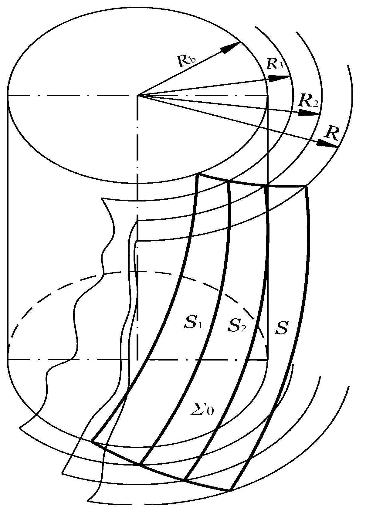
The invention discloses a design method of a 0-degree tooth profile angle helical tooth finish turning gear shaving cutter. The design method comprises the following steps of: (1) confirming a radius Rb of a base circle: according to the structure of a used machine tool and a cutter, confirming the Rb; (2) selecting value of a base circle helical angle beta b 0: beta b 0 being from 10 degrees to 20 degrees; (3) confirming the helical direction which is consistent with the helical direction of a machining gear; (4) preliminarily calculating the number of teeth z0 of the cutter; (5) accounting an actual base circle helical angle; (6) confirming a radius R of an outer circle: R=R*b+ delta R; (7) confirming the width B of the cutter; (8) confirming a cutter tooth groove spiral lead P; (9) confirming a cutter blade normal relief angle alpha N; (10) confirming a cutter tooth groove normal section angle epsilon, and value of the epsilon ranging from 25 degrees to 30 degrees; (11) confirming the tooth top width b of the cutter tooth: b=mn; (12) confirming the groove depth h of the cutter tooth: h= (2.25-2.3)mn; (13) confirming the radius r1 of a tooth top arc of the end face: r1=0.25mn; and (14) confirming the radius r2 of a groove bottom arc of the cutter tooth: r2= (0.25-0.3)mn.
Description
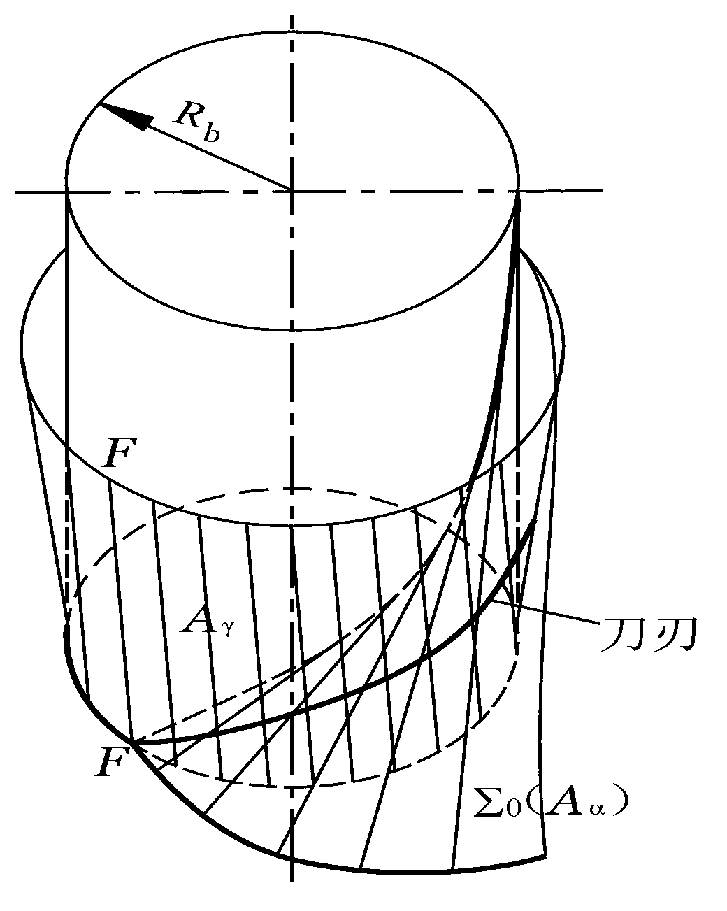
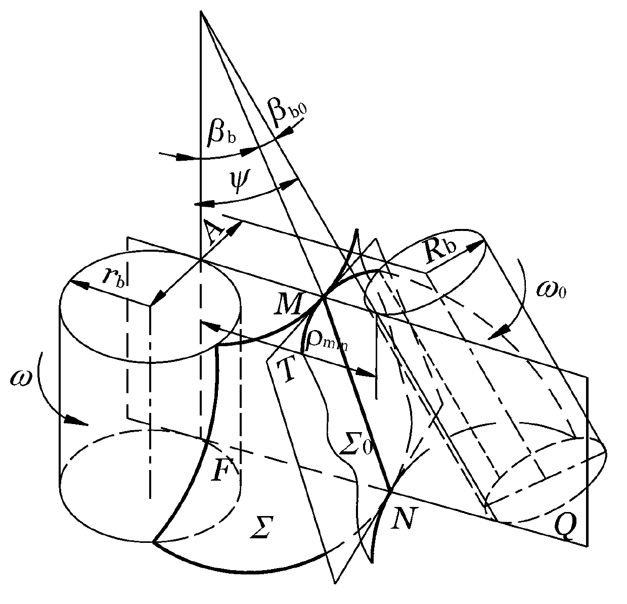
technical field [0001] The invention relates to a design method of a finish car gear shaving cutter, more precisely, the present invention relates to a design method of a 0° profile angle helical finish car gear shaving cutter. Background technique [0002] The fine car gear shaving method appeared after the general gear shaving method that has been widely used at present, and the history is not too long. ) and the gear to be machined are processed on the shaving tooth surface, still constitute a spatial cross-axis helical gear meshing transmission, and the tooth surface is finished by means of the relative sliding speed of the helical gear point mesh and the tooth surface, but there are significant differences between the two. [0003] 1. Generally, the tooth side of the shaving knife (that is, the flank of the tool) is provided with a chip groove (that is, the rake face of the tool) to form the cutting edge. The point on the cutting edge can only be cut to form the tooth s...
Claims
Login to View More Application Information
Patent Timeline
 Patent Type & Authority Applications(China)
IPC IPC(8): B23F21/28
Inventor 呼咏彭福华豆书强相明君
Owner JILIN UNIV

PatSnap Eureka turns technology decisions into work you can execute. Powered by our Innovation Knowledge Graph, it runs expert workflows across engineering, life sciences, materials and intellectual property. Get your review-ready output in minutes.


