Roots vacuum pump

A Roots vacuum pump and cavity technology, applied in the direction of pumps, pump components, rotary piston pumps, etc., can solve the problems of inability to use IC equipment, high power consumption, low ultimate vacuum, etc., and achieve long service life and energy saving. and space, reducing the effect of pulsating shock

Active Publication Date: 2013-05-15
SHENYANG SCI INSTR RES CENT CHINESE ACAD OF SCI
View PDF5 Cites 15 Cited by
  • Summary
  • Abstract
  • Description
  • Claims
  • Application Information

AI Technical Summary

Problems solved by technology

[0004] In order to overcome the shortcomings of the existing Roots pump technology, such as low ultimate vacuum, high power consumption, large volume, and inability to be used in IC equipment, the purpose of the present invention is to provide a Roots vacuum pump, which is a new type of Roots vacuum pump suitable for IC equipment. Pump

Method used


Image

  • Roots vacuum pump
  • Roots vacuum pump
  • Roots vacuum pump

Examples


Embodiment Construction

[0023] The present invention will be further described below in conjunction with the accompanying drawings.

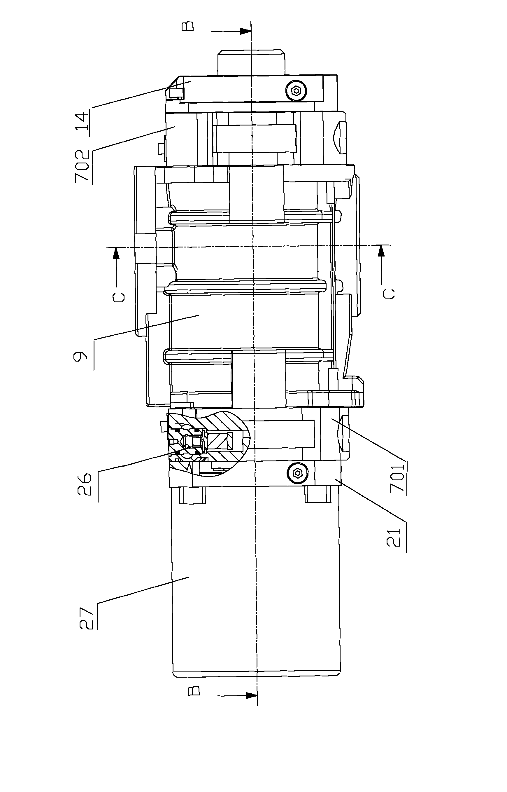
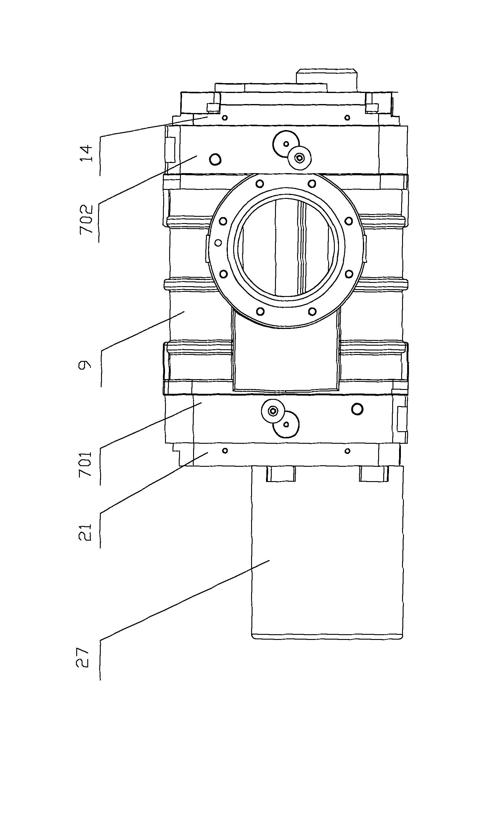
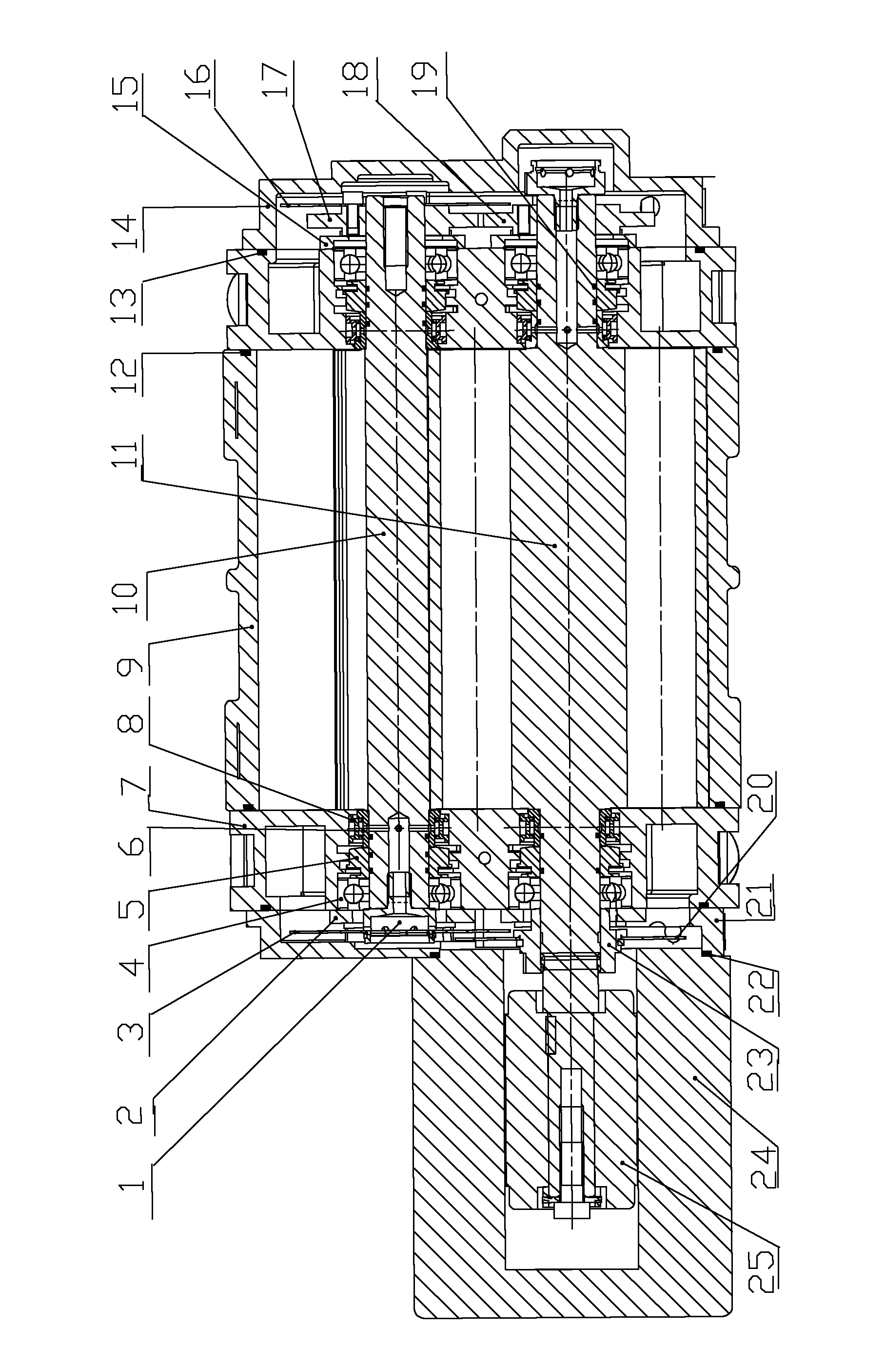
[0024] Such as Figure 1~4 As shown, the present invention includes motor 27, front bearing cavity 701, rear bearing cavity 702, Roots cavity 9 and gear cavity 14, wherein front bearing cavity 701 and rear bearing cavity 702 are located at Roots cavity 9 The two sides of the gear cavity 14 are connected with the rear bearing cavity 702; the Roots cavity 9 is provided with intake and exhaust holes, and the active rotor shaft 11 and the driven rotor shaft 10 are arranged in it, and the active rotor shaft 11 The corresponding Roots driving rotor 28 and Roots driven rotor 29 are respectively arranged on the driven rotor shaft 10; one end of the driving rotor shaft 11 passes through the Roots cavity 9 and the front bearing cavity 701 to connect with the motor 27, and the other One end passes through the Roots cavity 9 and the rear bearing cavity 702 and is placed in the ge...


PUM


Abstract

The invention relates to the technical field of vacuum pumps, and in particular relates to a roots vacuum pump. The vacuum pump comprises a motor, front and back bearing cavities, a roots cavity and a gear cavity, wherein the front and back bearing cavities are located at the both sides of the roots cavity, and the gear cavity is connected with the back bearing cavity; the roots cavity is provided with an air inlet and an air outlet and is internally provided with a driving rotor shaft and a driven rotor shaft; the driving rotor shaft and the driven rotor shaft are respectively and correspondingly provided with a roots driving rotor and a roots driven rotor; one end of the driving rotor shaft is connected with the motor, and the other end of the driving rotor shaft is provided with a driving gear; one end of the driven motor shaft is provided with a driven gear which is in transmission connection with the driving gear and accommodated in a gear box; and the front bearing cavity and the back bearing cavity are internally provided with bearings and bearing support rings which are sleeved and fixed at the both ends of the driving rotor shaft and the driven rotor shaft. The roots vacuum pump has the advantages of being small in size, high in pumping speed, energy-saving, space-saving, and applicable to IC equipment.

Description

technical field [0001] The invention relates to the technical field of vacuum pumps, in particular to a Roots vacuum pump. Background technique [0002] Roots vacuum pumps evolved from Roots blowers, including high vacuum multistage Roots pumps, medium vacuum Roots booster pumps and dry Roots pumps with direct exhaust to the atmosphere. They are widely used in chemical industry, papermaking, metallurgy, film preparation, Food and other industries are also commonly used in the IC equipment industry as a vacuum pump. The research and manufacture of Roots vacuum pumps in China was earlier, but there are not many Roots dry pumps suitable for the strict requirements of the IC equipment industry, resulting in long-term dependence on imports for this equipment. [0003] The air-cooled Roots dry pump meets many requirements of the IC equipment industry, such as high working temperature, long-term stable operation, low noise, simple maintenance, clean and oil-free, etc. It is a dry ...

Claims


Application Information

Patent Timeline
Patent Type & Authority Applications(China)
IPC IPC(8): F04C18/14F04C27/00F04C29/00
Inventor 雷震霖王光玉刘在行
Owner SHENYANG SCI INSTR RES CENT CHINESE ACAD OF SCI
Why Eureka
Try Eureka