crankshaft damper

A crankshaft shock absorber and crankshaft technology, applied in the direction of rotation vibration suppression, etc., can solve the problems that the crankshaft torsional vibration cannot be completely eliminated, the uneven rotation of the crankshaft shock absorber, and the tension fluctuation of the accessory belt, etc., so as to facilitate the design and layout and reduce the engine cost, the effect of favorable austerity

Inactive Publication Date: 2016-12-28
SAIC MOTOR
View PDF11 Cites 0 Cited by
  • Summary
  • Abstract
  • Description
  • Claims
  • Application Information

AI Technical Summary

Problems solved by technology

[0005] However, the existing crankshaft shock absorber still cannot completely eliminate the influence of crankshaft torsional vibration and crankshaft rolling vibration, so that the crankshaft shock absorber still has uneven rotation, resulting in tension fluctuations in the accessory belt driven by it.

Method used


Image

  • crankshaft damper
  • crankshaft damper
  • crankshaft damper

Examples


Embodiment 1

[0058] Crankshaft shock absorber for in-line 4-cylinder engine

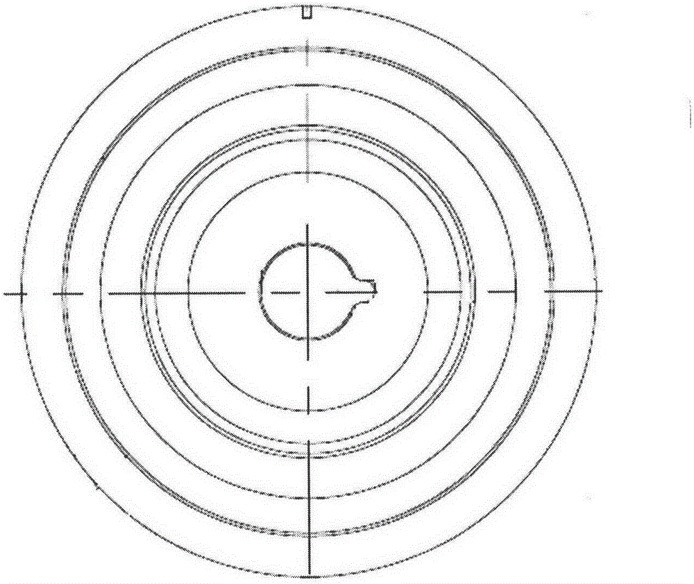
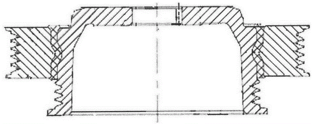
[0059] Such as Figure 9 , 10 As shown, the outer ring of the crankshaft shock absorber in Embodiment 1 is approximately elliptical as a whole, and the inner and outer rings are integrally formed without a rubber damping ring. It can be made by stamping and spinning steel plates.

Embodiment 2

[0061] Crankshaft shock absorber for in-line 4-cylinder engine

[0062] Such as Figure 11 , 12 As shown, the outer ring of the crankshaft shock absorber in Embodiment 2 is approximately elliptical as a whole, the outer ring is connected to the inner ring through a rubber damping ring, and the inner ring is connected to the crankshaft.

Embodiment 3

[0064] Crankshaft shock absorber for in-line 4-cylinder engine

[0065] Such as Figure 13 , 14 As shown, the outer ring of the crankshaft shock absorber in Embodiment 3 is approximately elliptical as a whole, the outer ring is connected to the inner ring through a rubber damping ring, and the outer ring is connected to the crankshaft.


PUM


Abstract

The invention provides a crankshaft damper which comprises an outer ring (1) and an inner ring (2). The outer ring (1) is wholly in a non-regular round shape. The crankshaft damper can reduce effect of rolling vibration and torsion vibration of a crankshaft on tension of a front end accessory belt so as to prolong the service life of the belt.

Description

technical field [0001] The invention relates to a crankshaft damper for an engine. Background technique [0002] During the operation of the engine, huge pressure will be generated when the cylinder is ignited and burned, and the pressure is transmitted to the crankshaft through the crank connecting rod mechanism to drive the crankshaft to rotate. Since the instantaneous huge pressure generated by the combustion in each cylinder of the engine will have an impact on its crankshaft, therefore, the crankshaft will produce uneven rotation during the working cycle, and the number of peak angular speeds of rotation corresponds to the number of ignitions in the working cycle. This uneven rotation of the crankshaft is called crankshaft roll. In addition, due to the certain torsional stiffness of the crankshaft, the force acting on the crank throw at the front end will quickly cause the front end of the crankshaft to twist and deform relative to the rear end, and when the force disa...

Claims


Application Information

Patent Timeline
Patent Type & Authority Patents(China)
IPC IPC(8): F16F15/10
Inventor 王京堂平银生郑重郑志强张小虎姜耀全薛理心
Owner SAIC MOTOR
Why Eureka
Try Eureka