Motor control device, robot hand, robot, and motor control method

A technology of motor control and manipulator, applied in the direction of program control manipulator, motor control, AC motor control, etc., can solve the problem that the movable part cannot move.

Active Publication Date: 2013-05-15
SEIKO EPSON CORP
View PDF10 Cites 24 Cited by
  • Summary
  • Abstract
  • Description
  • Claims
  • Application Information

AI Technical Summary

Problems solved by technology

Furthermore, when the manipulator grasps the object to be grasped or inserts a componen

Method used


Image

  • Motor control device, robot hand, robot, and motor control method
  • Motor control device, robot hand, robot, and motor control method
  • Motor control device, robot hand, robot, and motor control method

Examples


no. 1 Embodiment approach

[0048] In this embodiment, according to Figure 1 to Figure 6 , the characteristic examples of the motor control device and the manipulator using the motor control device will be described.

[0049] manipulator

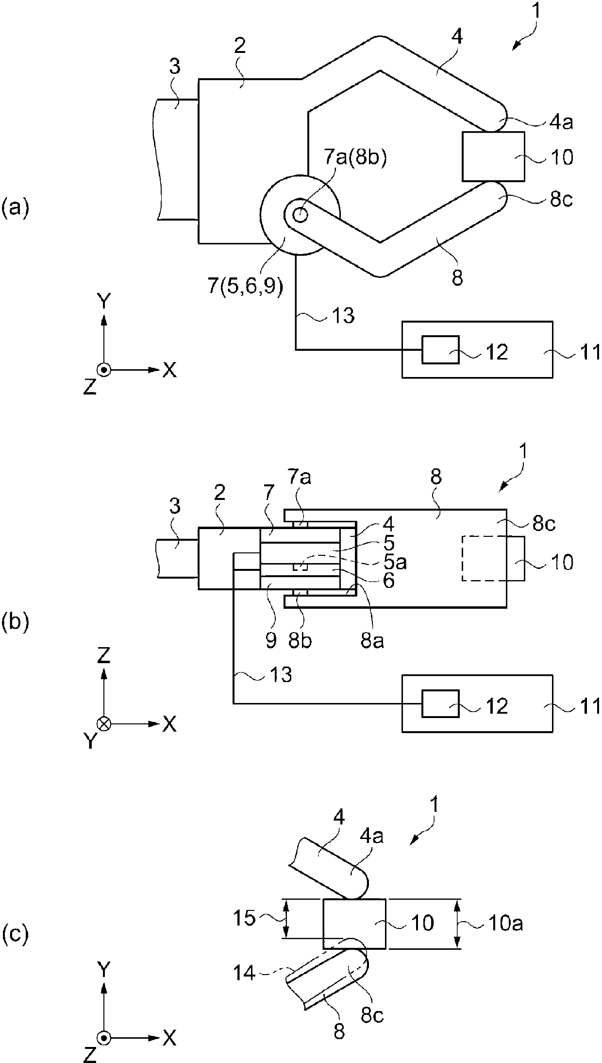
[0050] figure 1 (a) is a schematic plan view showing the configuration of the manipulator, figure 1 (b) is a schematic side view showing the configuration of the manipulator. figure 1 (c) is a schematic enlarged view showing main parts of the fingers of the manipulator. Such as figure 1 (a) and figure 1 As shown in (b), the robot hand 1 includes a cuboid hand body 2 . Let the longitudinal direction of the hand main body 2 be the Y direction, and let the direction perpendicular to the Y direction be the X direction. In addition, let the thickness direction of the hand main body 2 which is perpendicular to the X direction and the Y direction be the Z direction.

[0051] On the -X side surface of the hand body 2 , the hand body 2 is connected to an arm 3 , and th...

no. 2 Embodiment approach

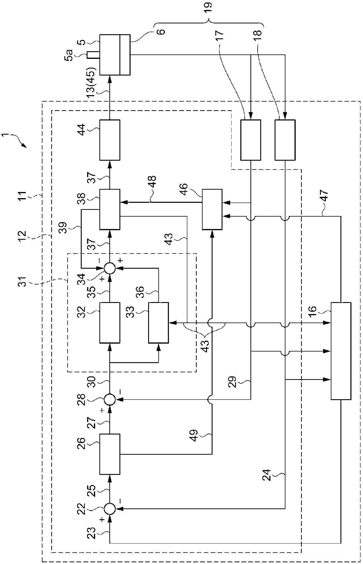
[0122] Next, use Figure 7 A block diagram showing the configuration of the control device and Figure 4 A timing chart for explaining a gripping method in a gripping operation, and an embodiment of a characteristic example of a motor control device and a manipulator using the motor control device will be described.

[0123] This embodiment differs from the first embodiment in that the limit value setting unit uses the torque command signal 37 to determine whether the movable finger 8 is in contact with the object to be grasped 10 . Furthermore, the description of the same points as those of the first embodiment will be omitted.

[0124] That is, in this embodiment, if Figure 7 As shown, the manipulator 63 includes a control device 64 as a control unit, and the control device 64 has a motor control device 65 . The motor control device 65 includes a limit value setting unit 66 corresponding to the limit value setting unit 46 of the first embodiment. The limit value setting...

no. 3 Embodiment approach

[0132] Next, use Figure 8 as well as Figure 9 , an embodiment of a characteristic example of the manipulator and the robot equipped with the manipulator will be described. Figure 8 (a) is a schematic plan view showing the configuration of the manipulator, Figure 8 (b) is a schematic enlarged view showing main parts of the fingers of the manipulator. Figure 9 It is a schematic plan view showing the configuration of a robot equipped with a manipulator.

[0133] This embodiment differs from the first embodiment in that a plurality of movable fingers pinches and grasps an object to be grasped. Furthermore, the description of the same points as those of the first embodiment will be omitted.

[0134] That is, in this embodiment, if Figure 8As shown in (a), the robot hand 70 includes a rectangular parallelepiped hand body 71 . Let the longitudinal direction of the hand main body 71 be the Y direction, and let the direction perpendicular to the Y direction be the X directi...


PUM


Abstract

A motor control device controls a motor using an angle data signal and a rotational speed signal output from a rotation detector detecting a rotation state of a rotating shaft of the motor. The motor control device includes a speed control unit that outputs a torque instruction signal corresponding to a difference between the rotational speed of the rotating shaft and a speed instruction using the speed instruction of the rotating shaft and the rotational speed signal, a limit value setting unit that sets a torque limit value indicating the maximum value of the torque applied to the rotating shaft, and a torque limit control unit that limits the torque of the rotating shaft driven by the torque instruction signal to the torque limit value or less.

Description

technical field [0001] The invention relates to a motor control device, a manipulator, a robot and a motor control method. Background technique [0002] A method of controlling the stop position of a movable part using a servo motor in a robot or a working machine is widely used. Furthermore, when the manipulator grasps the object to be grasped or inserts a component into the hole, the movable portion may not be able to move until it reaches a predetermined position. In this case, Patent Document 1 discloses a method in which a torque limit is set for a motor to control a movable part. Accordingly, this control method includes a storage means for storing a plurality of torque limit values, and switches the torque limit value for each operation performed by a motor to be driven or a movable part. [0003] In addition, Patent Document 2 discloses a method of improving the control performance of the rotational speed without changing the torque rapidly during the rotation of t...

Claims


Application Information

Patent Timeline
IPC IPC(8): H02P23/00B25J9/18B25J15/08B25J13/00G05B19/18H02P29/00
CPCB25J13/088B25J9/1612B25J13/00B25J13/085H02P7/18H02P6/16H02P23/0004H02P21/13H02P21/14H02P23/0027H02P27/06H02P27/08
Inventor 濑下勇佐藤大辅
Owner SEIKO EPSON CORP
Why Eureka
Try Eureka