Rotary type clamping device

A clamping device, rotary technology, applied in the direction of positioning device, clamping, support, etc., can solve the problems of reduced processing efficiency, insufficient clamping, difficult workpieces, etc., to achieve low friction coefficient, firm clamping, high durability abrasive effect

Inactive Publication Date: 2013-05-22
CHONGQING MING SHIELD ELECTROMAGNETIC VALVE
View PDF0 Cites 4 Cited by
  • Summary
  • Abstract
  • Description
  • Claims
  • Application Information

AI Technical Summary

Problems solved by technology

Since the outer surface of most workpieces needs to be processed, in order to facilitate the processing of the workpiece by the machine tool, the current clamping device has a complex structure and is inconvenient to operate, making it difficult to clamp the workpiece, or the clamping is not firm enough to make it clamp The effect is not good, which greatly reduces the processing efficiency and has a great impact on production

Method used


Image

  • Rotary type clamping device

Examples


Embodiment Construction

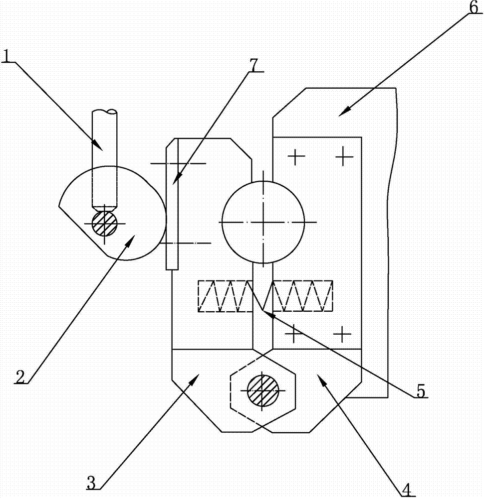
[0008] As shown in Figure 1, the rotary clamping device of the present invention comprises a rotating handle 1, a cam 2, a movable jaw 3, a fixed jaw 4, a spring 5, a base 6, a hardened friction pad 7, a movable jaw 3 and a fixed The lower end of the jaw 4 is hinged, a spring 5 is provided between the movable jaw 3 and the fixed jaw 4, the fixed jaw 4 is fixed on the base 6 by bolts, the upper end of the movable jaw 3 fits with the cam 2, and the upper end of the cam 2 There is a hardened friction pad 7 in contact with the movable jaw 3 , the cam 2 is hinged to the base 6 , and the cam 2 is welded with a rotating handle 1 . When the workpiece is placed between the movable jaw 3 and the fixed jaw 4, the cam 2 is rotated clockwise by turning the handle 1. Under the transmission of the rotating cam 2, the movable jaw 3 is drawn towards the fixed jaw 4, and the workpiece is clamped. Tight; when the cam 2 is loosened, since the spring 5 is compressed when the workpiece is clamped,...


PUM


Abstract

The invention discloses a rotary type clamping device and relates to a clamping device. The rotary type clamping device comprises a base seat, a rotary handle, a cam, two clamping jaws and a harden friction pad. A movable clamping jaw is hinged with a fixed camping jaw. A spring is arranged between the movable clamping jaw and the fixed clamping jaw. The fixed clamping jaw is fixed on the base seat through a bolt. The movable clamping jaw is fit with the cam. The harden friction pad is arranged on the cam, wherein the harden friction pad is fit with the movable clamping jaw in a contact mode. The cam is hinged with the base seat. The cam is in welded with the rotary handle. The rotary type clamping device overcomes the defect that a workpiece cannot be clamped or the workpiece cannot be fastened when clamped. So processing efficiency is improved and service life is prolonged.

Description

technical field [0001] The invention relates to the technical field of clamping devices, in particular to a rotary clamping device. Background technique [0002] At present, clamping devices are widely used in mechanical processing. The clamping device is a mechanism that makes the positioned workpiece reliably fixed on the positioning element during the entire processing process without changing its position. When clamping the workpiece, it is not allowed to damage the positioning of the workpiece, and there should be enough rigidity to ensure the necessary clamping force, but it should not damage the processed surface of the workpiece or deform the workpiece, so as to ensure the processing accuracy. Since the outer surface of most workpieces needs to be processed, in order to facilitate the processing of the workpiece by the machine tool, the current clamping device has a complex structure and is inconvenient to operate, making it difficult to clamp the workpiece, or t...

Claims


Application Information

Patent Timeline
Patent Type & Authority Applications(China)
IPC IPC(8): B23Q3/00
Inventor 姜静慧
Owner CHONGQING MING SHIELD ELECTROMAGNETIC VALVE
Why Eureka
Try Eureka