Vacuum sucker

A technology of vacuum suction cups and cavities, which is applied in the direction of manipulators, chucks, manufacturing tools, etc., can solve problems such as suction cups losing their effect, calendar rings that cannot meet production requirements, and the task of picking and placing small-diameter circular watch parts. Replacement, strong practicability, and convenient processing

Inactive Publication Date: 2013-05-22
XIAMEN UNIV
View PDF6 Cites 25 Cited by
  • Summary
  • Abstract
  • Description
  • Claims
  • Application Information

AI Technical Summary

Problems solved by technology

With the increase of production and quality requirements for watch calendar rings, the way of manually picking and placing calendar rings can no longer meet the production requirements
[0003] When ordinary trumpet-shaped vacuum suction cups absorb ring parts, because the contact surface with the parts contains a central hole, the suction cup will lose its effect due to air leakage in the center hole, so it cannot complete the task of picking and placing small diameter ring watch parts

Method used


Image

  • Vacuum sucker
  • Vacuum sucker
  • Vacuum sucker

Examples


Embodiment Construction

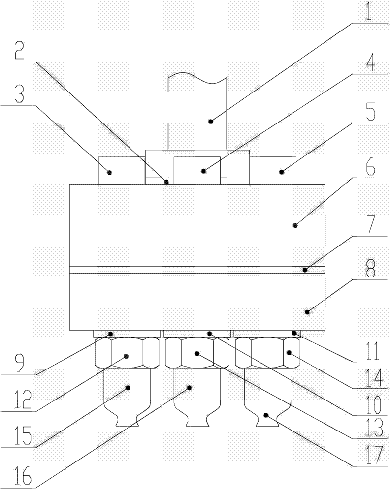
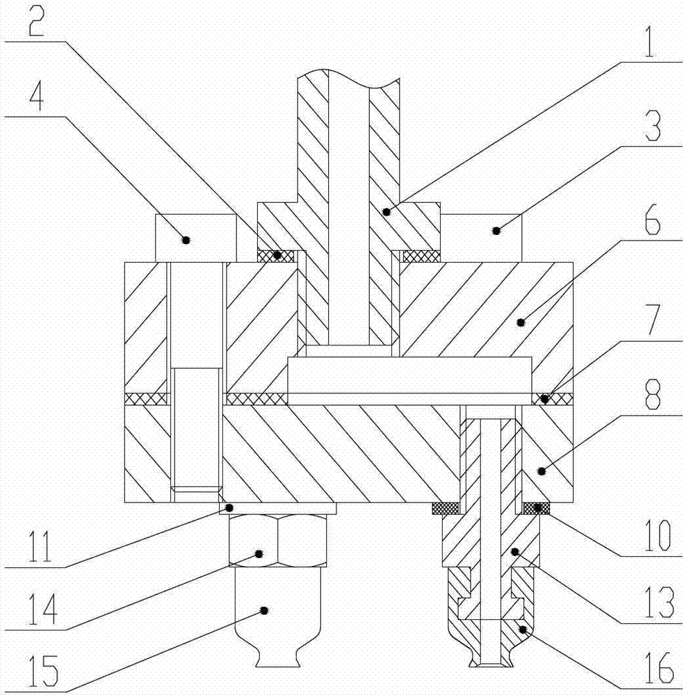
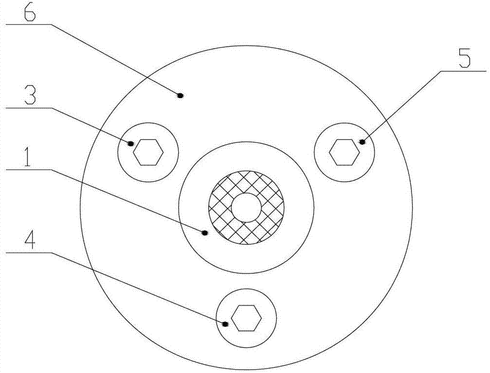
[0022] see figure 1 with 2 , The embodiment of the present invention is provided with a connecting plate (including an upper plate 6 and a lower plate 8 ), three metal suction heads 12-14 and three rubber suction nozzles 15-17.

[0023] The upper plate 6 and the lower plate 8 are locked by connecting screws 3-5, and a gasket 7 is installed between the upper plate 6 and the lower plate 8 to prevent air leakage. The lower surface of the upper plate 6 is provided with a trident-shaped (Y-shaped) groove 61, and a cavity is formed between the lower surface of the upper plate 6 and the lower plate 8, and serves as a gas channel. The center of the upper plate 6 is provided with a threaded through hole, which is not only the installation hole for the external suction device joint 1 and the vacuum suction cup, but also the vacuum port of the vacuum suction cup. Sealing gasket 2 is housed between the upper plate 6 upper end surface of external suction device joint 1 and connecting pla...


PUM


Abstract

The invention provides a vacuum sucker and relates to a vacuum sucker achieving convenient and rapid picking and placing of a small diameter annular watch component on an automatic watch production line. A connecting plate, at least 2 metal suckers and at least 2 rubber suction nozzles are arranged on the vacuum sucker. An upper plate and a lower plate are arranged on the connecting plate. The upper plate is connected with the lower plate through a fastening piece in a locking mode. A thread through hole is arranged in the upper plate. A groove is arranged in the lower surface of the upper plate. A hollow cavity is formed between the upper plate and the lower plate. At least 2 metal sucker installing holes are arranged in the lower plate. The thread through hole and the hollow cavity are communicated with the metal sucker installing hole. A metal sucker is connected with each metal sucker installing hole. A rubber suction nozzle is connected with each metal sucker. Center through holes are uniformly arranged in the metal sucker and the rubber nozzle. Due the facts that a separated type structure is adopted, the connecting plate and the metal sucker are all made of metal materials,the vacuum sucker is convenient to machine, low in cost, convenient to dismantle and convenient to clean. The component damage is easy to change. The vacuum sucker is strong in practicality.

Description

technical field [0001] The invention relates to a suction cup, in particular to a vacuum suction cup suitable for conveniently picking and placing small-diameter circular watch parts (such as watch calendar rings, week calendar rings, etc.) in an automatic watch production line. Background technique [0002] Watch calendar rings (or weekly calendar rings, etc.) are small-diameter watch parts with circular cross-sections and generally have obvious structural holes. The walls are thin, light, and not resistant to scratches. They are not suitable for direct contact with hard workpieces. In the watch production process, it is necessary to print numbers, letters or patterns on the surface of the watch calendar ring, and install the calendar ring on the watch movement. In the existing production, the picking and placing of this kind of parts is usually done manually, and the production efficiency is low. With the improvement of watch calendar ring production and quality requireme...

Claims


Application Information

Patent Timeline
Patent Type & Authority Applications(China)
IPC IPC(8): B25J15/06
Inventor 胡国清邓晓帆兰丕祥叶元杰廖仲生侯凤媛
Owner XIAMEN UNIV
Why Eureka
Try Eureka