Electromagnetic brake

A technology of electromagnetic brakes and brake shoes, which is applied in the direction of brake actuators, gear transmission mechanisms, hoisting devices, etc., and can solve problems such as affecting life, high processing accuracy requirements, and elevator safety risks

Active Publication Date: 2013-05-22
HANGZHOU HUNING ELEVATOR PARTS CO LTD +1
View PDF4 Cites 6 Cited by
  • Summary
  • Abstract
  • Description
  • Claims
  • Application Information

AI Technical Summary

Problems solved by technology

[0002] The existing block type electromagnetic brakes for elevators, the braking gap between the brake shoe and the brake drum is between 0.2 and 0.7 mm, and the brake needs to provide the braking positive force required to effectively ensure the safe braking of the elevator at the maximum gap. At the same time, the brake also needs to ensure that the brake can be opened in time and quickly when the coil is energized. Therefore, the magnetic circuit of the brake needs sufficient magnetic circuit cross-sectional area and magnetomotive force to provide sufficient electromagnetic attraction, so that the brake is large in size and The weight is heavy, the amount of enameled wire is large, and the electric power required to open the brake is large; and because of the small stroke, it is difficult to realize the monitoring of the brake opening state and the wear state of the brake shoe in a stable and reliable way, and it is difficult for the on-site personnel to monitor the wear status of the brake shoe. Evaluate and adjust the brakes in time, so there may be a safety ris...

Method used


Image

  • Electromagnetic brake
  • Electromagnetic brake
  • Electromagnetic brake

Examples


Embodiment Construction

[0056] Embodiments of the present invention will be described in detail below in conjunction with the accompanying drawings.

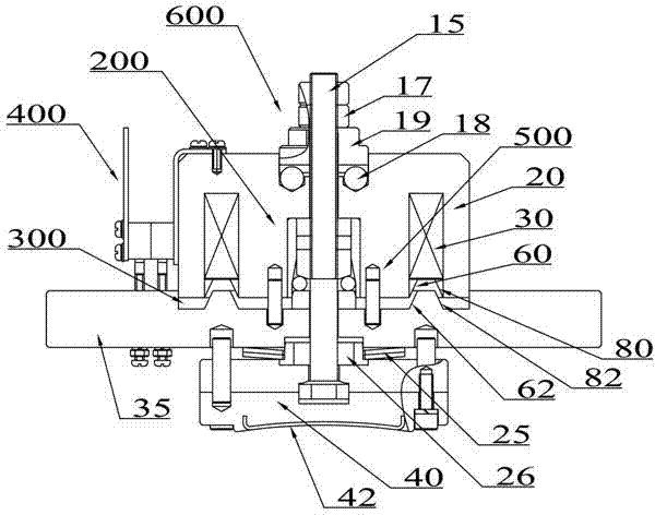
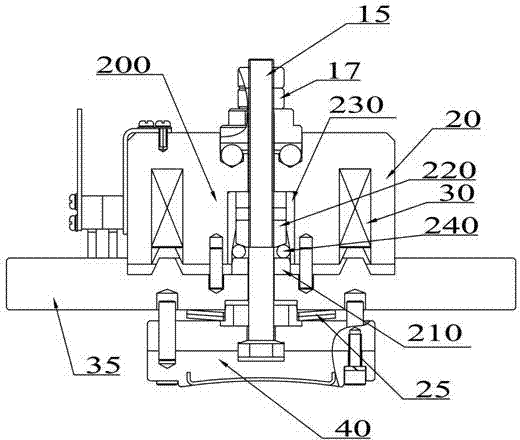
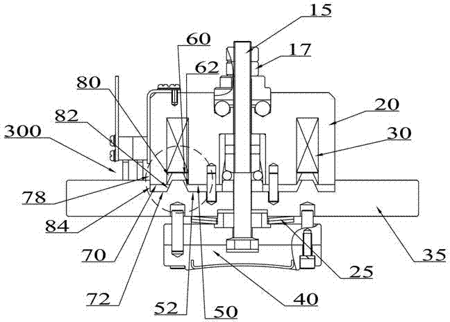
[0057] see figure 1 , the electromagnetic brake in this embodiment includes a yoke 20, an electromagnetic coil 30 arranged in the yoke 20, an armature 35, a reset elastic member 25, a brake shoe 40, an inclined surface booster mechanism 200, and an end structure of a disc proportional electromagnet 300 , electromagnetic coil series-parallel switching circuit 400 , pin positioning and air resistance buffer device 500 , and manual opening device 600 .

[0058] The fastening bolt 15 runs through the yoke 20 , a manual opening device 600 is provided between one end of the fastening bolt 15 and the yoke 20 , and the other end of the fastening bolt 15 passes through the armature 35 and is fixedly connected with the brake shoe 40 .

[0059] see Figure 18 The manual opening device 600 includes a ball 18, a driving slope 19, a fastening nut 17, and a lock nu...


PUM


Abstract

The invention discloses an electromagnetic brake which comprises a magnet yoke and the like. An electromagnetic coil is arranged inside the magnet yoke. A fastening bolt penetrates the magnet yoke and an armature in sequence, and then the fastening bolt is fixedly connected with a brake shoe. The magnet yoke is opposite to the armature. The armature can move relative to the magnet yoke. A reset elastic component is abutted between the armature and the brake shoe; and/or a slope force amplification mechanism is arranged inside the magnet yoke. The magnet yoke directly drives the slope force amplification mechanism. The electromagnetic force of the magnet yoke is amplified by beta times through the slope force amplification mechanism; and/or a groove with a cone-shaped side surface is formed in the end portion, opposite to the armature, of the magnet yoke. Correspondingly, a boss with a cone-shaped side surface is formed in the corresponding end portion, opposite to the magnet yoke, of the armature and matched with the groove; and/or a plurality of electromagnetic coils are arranged, the connection mode of the electromagnetic coils can be converted between the series connection and the parallel connection, conversion of the series connection and the parallel connection of the electromagnetic coils can be achieved through an electromagnetic coils series-parallel connection conversion circuit; and/or a pin-positioning air resistance-buffering device is arranged between the armature and the brake shoe to integrates the pin positioning and air resistance buffering into a whole.

Description

technical field [0001] The invention belongs to the technical field of electromagnetic brake manufacturing, and in particular relates to a block type electromagnetic brake for elevators. Background technique [0002] The existing block type electromagnetic brakes for elevators, the braking gap between the brake shoe and the brake drum is between 0.2 and 0.7 mm, and the brake needs to provide the braking positive force required to effectively ensure the safe braking of the elevator at the maximum gap. At the same time, the brake also needs to ensure that the brake can be opened in time and quickly when the coil is energized. Therefore, the magnetic circuit of the brake needs sufficient magnetic circuit cross-sectional area and magnetomotive force to provide sufficient electromagnetic attraction, so that the brake is large in size and The weight is heavy, the amount of enameled wire is large, and the electric power required to open the brake is large; and because of the small ...

Claims


Application Information

Patent Timeline
IPC IPC(8): B66D5/00F16D65/14F16D121/20F16D127/04F16D127/10
Inventor 吕崇耀邹家春
Owner HANGZHOU HUNING ELEVATOR PARTS CO LTD
Why Eureka
Try Eureka