
Chuck type split bolt formwork erecting method

A technology for pulling bolts and formwork methods, which is applied in the treatment of formwork, the preparation of building components on site, and construction, etc., can solve the problems of inconvenient erection and dismantling, increased costs, inconvenient formwork support and dismantling, etc. Good reinforcement effect and convenient construction

Inactive Publication Date: 2013-05-22
ZHONGTIAN CONSTR GROUP
View PDF6 Cites 3 Cited by
  • Summary
  • Abstract
  • Description
  • Claims
  • Application Information

AI Technical Summary

Problems solved by technology

Deformation joints are often small in width, which causes inconvenience to the formwork support and removal of structures on both sides of the deformation joint
Now the conventional formwork system is often used, which is extremely inconvenient to set up and dismantle, and due to space constraints, the pull bolts must be misplaced; there is also a method of filling the deformation joints with rigid foam boards, but the reinforcement effect is not ideal, and the foam boards Unable to recycle, additional cost

Method used


Image

  • Chuck type split bolt formwork erecting method
  • Chuck type split bolt formwork erecting method
  • Chuck type split bolt formwork erecting method

Examples


Embodiment Construction

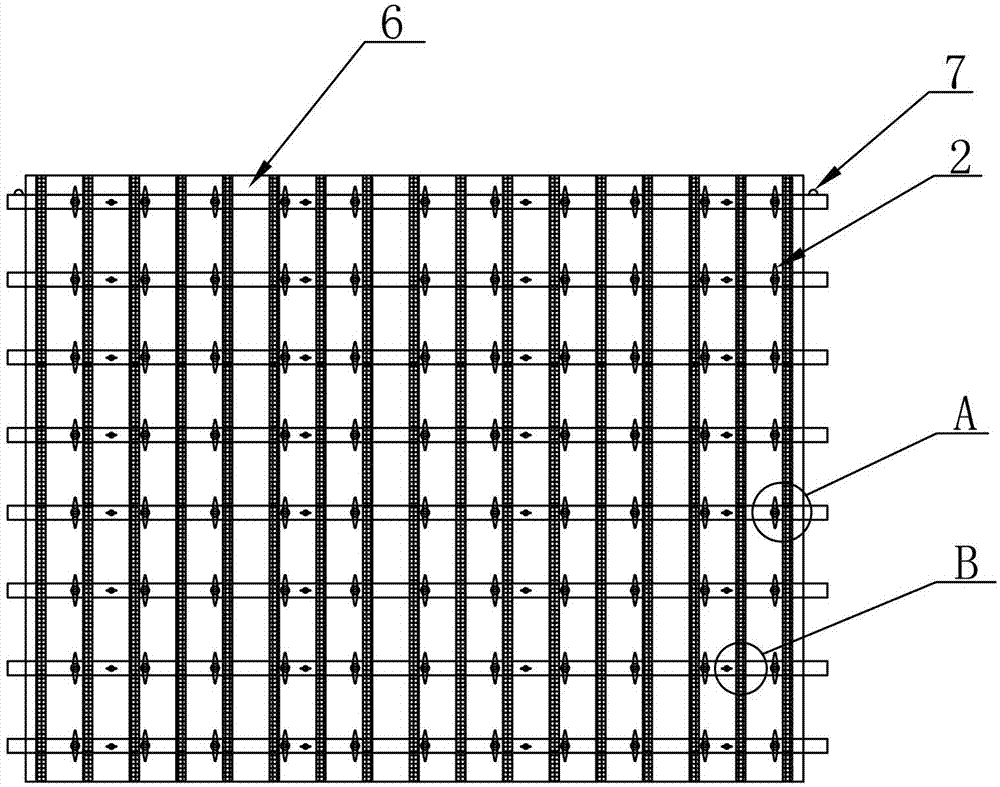
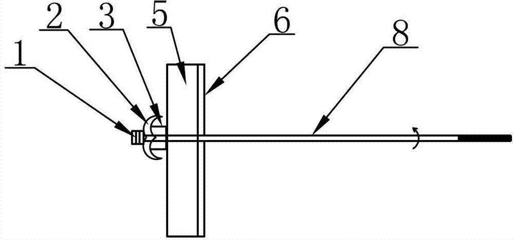
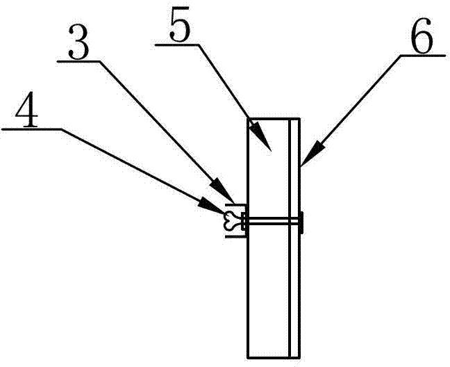
[0021] see figure 1 , figure 2 and image 3 , a clamping head type pull bolt formwork method disclosed by the present invention, comprising the following steps:

[0022] Step 1, prepare the nut 1, the mountain-shaped card 2 and the channel steel 3 with the lifting ring 7, and connect the nut 1, the mountain-shaped card 2 and the channel steel 3 to form a chuck;

[0023] Step 2: Make screw holes on the side formwork of the wall panel and install the PVC pipe;

[0024] Step 3, prepare the wooden square 5 and the formwork 6 again, and fix the channel steel 3, the wooden square 5 and the formwork 6 through the screws 4 to form a whole;

[0025] Step 4, hoist the installed template 6 into the deformation joint through the lifting ring 7 arranged on the channel steel 3;

[0026] Step 5, pass the pull screw 8 from the indoor to the outdoor side through the PVC pipe, and align the hole with the chuck, and tighten the handle of the screw 8 and the nut 1 for installation and reinfo...


PUM


Abstract

The invention discloses a chuck type split bolt formwork erecting method. The method comprises the following steps: nuts, clamps shaped like a Chinese character 'shan' and channel steels with rings are prepared, chucks are formed by connection of the nuts, the clamps shaped like the Chinese character 'shan' and the channel steels; screw holes are formed in the side formworks of wallboards; wood beams and formworks are prepared, the channel steels, the wood beams and the formworks are fixed to form a whole through screws; the installed formworks are hung into deformation joint portions through the rings arranged on the channel steels; split screws penetrate from the interior side to exterior side through polyvinyl chloride (PVC) pipes, the split screws penetrate through the screw holes of the chucks, handles of screws are rotated to be screwed with the nuts so as to conduct installing reinforcement; formworks inside the wallboards are reinforced, the concretes are poured after passed inspection; the formworks on the inner side of the wallboards are reinforced, after the concrete is poured and maintained, the handles of the screws are screwed, the formworks are dismounted, the chucks dropped in the process of dismounting are collected, and the dismounted formworks can be used repeatedly. The chuck type split bolt formwork erecting method has the advantages of being convenient to construct and good in reinforcing effect.

Description

technical field [0001] The invention relates to the technical field of building formwork, in particular to a method for supporting formwork with clamping head type pull bolts. Background technique [0002] In order to prevent cracks or damage to buildings due to factors such as temperature changes, uneven foundation settlement, and earthquakes, deformation joints are designed in advance at deformation-sensitive parts to disconnect buildings. Deformation joints are often small in width, which causes inconvenience to the formwork support and removal of structures on both sides of the deformation joint. Now the conventional formwork system is often used, which is extremely inconvenient to set up and dismantle, and due to space constraints, the pull bolts must be misplaced; there is also a method of filling the deformation joints with rigid foam boards, but the reinforcement effect is not ideal, and the foam boards Unable to recycle, additional cost will be charged. Contents ...

Claims


Application Information

Patent Timeline
Patent Type & Authority Applications(China)
IPC IPC(8): E04G21/00E04G19/00
Inventor 曹跃军张敬黎竹永良吴栋平
Owner ZHONGTIAN CONSTR GROUP
Learn More