Antenna array calibration method and system

A technology of antenna array and calibration method, which is applied in the field of communication, can solve problems such as data distortion, and achieve the effects of improving precision, accurate comparison results, and avoiding distortion

Active Publication Date: 2013-05-22
DATANG MOBILE COMM EQUIP CO LTD
View PDF6 Cites 4 Cited by
  • Summary
  • Abstract
  • Description
  • Claims
  • Application Information

AI Technical Summary

Problems solved by technology

[0006] The embodiment of the present invention discloses an antenna array calibration method and system to solve the problem of data distortion in the background technology

Method used


Image

  • Antenna array calibration method and system
  • Antenna array calibration method and system
  • Antenna array calibration method and system

Examples


Embodiment 1

[0058] A method for calibrating an antenna array disclosed in an embodiment of the present invention is introduced in detail.

[0059] refer to Image 6 , shows a flowchart of a method for calibrating an antenna array in an embodiment of the present invention.

[0060] Step 100, receiving calibration information from a digital signal processing unit in a first radio frame.

[0061] Wherein, the calibration information may specifically include: an average power value of the calibration sequence, a known number of symbols in which the calibration sequence is located, and a known calibration enable signal.

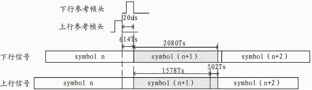
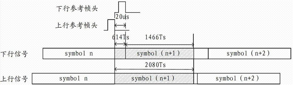
[0062] The average power value of the calibration sequence can be calculated by the digital signal processing unit based on all known data of the calibration sequence. Specifically, after the DSP receives the calibration trigger signal from the upper layer, it takes all the data of the calibration sequence (2080 sampling points in total) and calculates the average power val...

Embodiment 2

[0076] A method for calibrating an antenna array disclosed in an embodiment of the present invention is introduced in detail.

[0077] refer to Figure 7 , shows a flowchart of a method for calibrating an antenna array in an embodiment of the present invention.

[0078] Step 200, receiving calibration information from a digital signal processing unit in a first radio frame.

[0079] Wherein, the calibration information may specifically include: an average power value of the calibration sequence, a known number of symbols in which the calibration sequence is located, and a known calibration enable signal.

[0080] The average power value of the calibration sequence is calculated by the digital signal processing unit based on all known data of the calibration sequence.

[0081] Step 202, inserting the known calibration sequence into normal data in the second radio frame.

[0082] The first radio frame is connected to the second radio frame, and the first radio frame is before...

Embodiment 3

[0101] An antenna array calibration system disclosed in the embodiment of the present invention is introduced in detail.

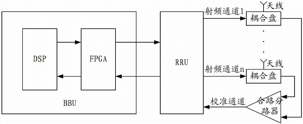
[0102] refer to Figure 8 , shows a structural diagram of an antenna array calibration system in an embodiment of the present invention.

[0103] The antenna array calibration system specifically may include:

[0104] A digital signal processing unit 30, and a BBU-FPGA unit 32.

[0105]The functions of each unit and the relationship between each unit are introduced in detail below.

[0106] The digital signal processing unit 30 is configured to calculate an average power value of the calibration sequence based on all data of the known calibration sequence.

[0107] The digital signal processing unit 30 is further configured to insert the known calibration sequence into the normal data in the second radio frame.

[0108] Specifically, the digital signal processing unit 30 inserts the known calibration sequence into two adjacent symbols in the second rad...


PUM


Abstract

The invention discloses an antenna array calibration method and a system. The problem of data distortion in background technology can be solved. The antenna array calibration method comprises the steps of receiving calibration information from a digital signal processor (DSP) in a radio frame, wherein the calibration information comprises an average power value of a calibration sequence, a known symbolic number where the calibration sequence lies and known calibration enable signals; calculating and obtaining the average power value of the calibration sequence by the DSP according to all data of the known calibration sequence; searching a calibration sequence in a second radio frame according to the symbolic number where the known calibration sequence lies and the known calibration enable signals and comparing the received average power value of the calibration sequence of the searched calibration sequence with known target gain; and regulating the gain according to the comparative result and completing antenna array calibration. The antenna array calibration method and the system improve the precision of the average power value of the calibration sequence, and avoid the condition of data distortion and the influence on the calibration sequence after a compression algorithm is introduced.

Description

technical field [0001] The embodiments of the present invention relate to the technical field of communications, and in particular, to a method and system for calibrating an antenna array. Background technique [0002] In the existing antenna array calibration method, in the downlink direction, the digital signal processing (Digital Signal Processing, DSP) unit inserts the calibration sequence into the position of the downlink baseband data protection time slot (Protect Period, GP), and then sends it to the baseband unit device (Base band Unit (BBU) Field Programmable Gate Array (Field-Programmable Gate Array, FPGA). In the uplink direction, the radio remote unit (Radio Remote Unit, RRU) switches through the switch, combines the calibration signal and the working signal, and then sends it to the RRU-FPGA. Therefore, for BBU-FPGA and RRU-FPGA, the working signal and the calibration signal are mixed together, and they are all processed according to the same process. And the ...

Claims


Application Information

Patent Timeline
Patent Type & Authority Applications(China)
IPC IPC(8): H04B7/06H04B7/08
Inventor 陈聃青耿贵杰
Owner DATANG MOBILE COMM EQUIP CO LTD
Why Eureka
Try Eureka