Method and device for monitoring electrical failure spark in real time

A technology for real-time monitoring and electrical faults, applied in the direction of measuring devices, measuring electricity, continuity testing, etc., can solve problems that affect the reliable operation of electrical equipment and generate sparks, and achieve the effects of wide practicability, reliable monitoring, and reliable operation

CN103123378AInactive Publication Date: 2013-05-29CHINA UNIV OF MINING & TECH +1
4 Cites 4 Cited by

Patent Information

Authority / Receiving Office
CN · China
Patent Type
Applications(China)
Current Assignee / Owner
Publication Date
2013-05-29
Estimated Expiration
Not applicable · inactive patent

Smart Images

  • Figure 1
    Figure 1
  • Figure 2
    Figure 2
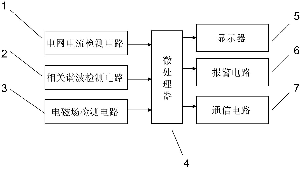
  • Figure 3
    Figure 3
Patent Text Reader

Abstract

Provided is a method and device for monitoring electrical failure spark in real time. The device is composed of a power grid current detecting circuit, a relevant harmonic detection circuit, an electromagnetic field detection circuit, a microprocessor, a displayer, a warning circuit and a communication circuit. Outputs of the power grid current detecting circuit, the relevant harmonic detection circuit and the electromagnetic field detection circuit are connected with an input end of the microprocessor, and electrical failure spark is comprehensively judged according to power grid current changes, harmonic analysis and an electromagnetic field signal. A failure occurring position is confirmed through positioning, reliable monitoring of electrical appliance spark is achieved under the condition that influence caused by suddenly increased load of surrounding electrical appliances is avoided, and conditions are created for timely failure elimination. The problem of real-time monitoring and positioning of the electrical failure spark caused by poor contact can be solved, the electrical failure spark can be timely monitored and founded, electrical safety is ensured, and the monitoring of safe environment of a hazardous place is facilitated. The method is simple in structure, reliable in operation and good in monitoring effect.
Need to check novelty before this filing date? Find Prior Art

Description

technical field

[0001] The invention relates to a method and device for real-time monitoring of sparks, in particular to a method and device for real-time monitoring of electrical fault sparks suitable for electrical fault diagnosis in industrial and mining enterprises or safety monitoring of explosive hazardous environments. technical background

[0002] The diagnosis of electrical open circuit fault is of great significance to ensure the safe operation of electrical equipment. At present, there is no good fault monitoring method, especially some electrical faults with poor contact and intermittent on and off, which will not only affect the reliable operation of electrical equipment, but also generate sparks and detonate explosive substances, especially in mine environments. The breaking spark is an important factor to detonate the gas. Therefore, real-time monitoring of electrical fault sparks is an urgent problem to be solved. Contents of the invention

[0003] Techni...

Examples

Embodiment Construction

[0018] An embodiment of the present invention will be further described below in conjunction with accompanying drawing:

[0019] Such as figure 1 As shown, the electrical fault spark real-time monitoring device of the present invention is mainly composed of grid current detection circuit 1, related harmonic detection circuit 2, electromagnetic field detection circuit 3, microprocessor 4, display 5, alarm circuit 6, communication circuit 7; The input end of processor 4 is connected with the output end of grid current detection circuit 1, relevant harmonic detection circuit 2 and electromagnetic field detection circuit 3 respectively, and the output end of microprocessor 4 is respectively connected with display 5, alarm circuit 6 and communication circuit 7 The input terminals are connected; the microprocessor 4 adopts single-chip microcomputer ATMEGA16 and has 8 A / D conversion circuits, which can meet the needs of multi-parameter detection.

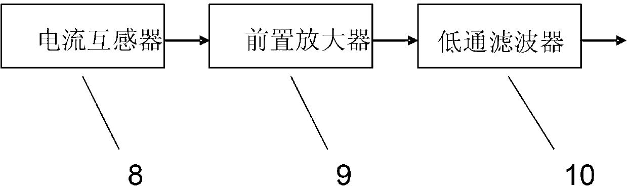
[0020] Such as figure 2 As shown...