Pumping well monitoring system and monitoring method

A monitoring system and pumping well technology, applied in the field of pumping well monitoring, can solve problems such as pump leakage, floating valve leakage, and damage to pumping well equipment

Pending Publication Date: 2017-05-17
XI'AN PETROLEUM UNIVERSITY
View PDF3 Cites 12 Cited by
  • Summary
  • Abstract
  • Description
  • Claims
  • Application Information

AI Technical Summary

Problems solved by technology

[0005] Swimming valve leakage, severe leakage or failure of the floating valve, lagging opening of the swimming valve, lagging closing of the swimming valve, leakage of the fixed valve, serious leakage or failure of the fixed valve, blockage of the fixed valve, Simultaneous leakage of the movable valve and the fixed valve, leakage of the oil pipe, breakage of the oil pipe, bending of the oil pipe, breakage of the sucker rod, pump leakage, uniform corrosion of the pump barrel, groove in the middle of the pump barrel, insufficient liquid supply to the pump, insufficient filling of the pump, gas influence, Air lock, insufficient liquid supply, upper dead center collision, plunger collision, vibration load, large inertial load, too small gap between plunger and pump barrel, plunger out of pump barrel, plunger partly out of pump barrel, plunger not Faults such as complete entry into the pump barrel, sand stuck, wax stuck, stuck pump, gear wear, belt slippage, pumping and jetting, and packing box too tight, etc. Once the above accidents occur in the pumping well with rod pumps, it will cause the use of related equipment in the pumping well. The reduction of service life and production shutdown, and serious accidents such as damage to pumping well equipment and casualties of pumping well staff
[0006] (2) Unbalance of pumping units in rod pump well system
[0007] During the working process of the pumping unit, there will be unbalanced problems of the pumping unit. When the pumping unit is unbalanced, it will cause the motor to do negative work, reducing the service efficiency and life of the motor; i

Method used


Image

  • Pumping well monitoring system and monitoring method
  • Pumping well monitoring system and monitoring method

Examples


Embodiment Construction

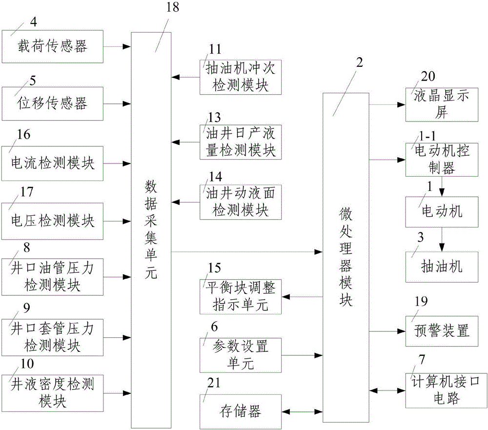
[0099] like figure 1 A pumping well monitoring system shown includes a monitoring device, a pumping unit 3 and an electric motor 1 for driving the pumping unit 3 to pump oil. The monitoring device includes a microprocessor module 2 and a microprocessor module 2 The connected memory 21, the motor controller 1-1 for controlling the motor 1 and the pumping well detection module for detecting the working condition of the monitored pumping well, the input terminal of the microprocessor module 2 is connected with a data acquisition unit 18 and a parameter setting unit 6 for parameter setting, the output terminal of the microprocessor module 2 is connected with a liquid crystal display 20, an early warning device 19 and a balance weight adjustment indicating unit 15, and the motor controller 1-1 and The microprocessor module 2 is connected, and the motor controller 1-1 is controlled by the microprocessor module 2;

[0100] The pumping well detection module includes a wellhead tubing...


PUM


Abstract

The invention discloses a pumping well monitoring system and a monitoring method. The monitoring system comprises a monitoring device, a pumping unit and an electric motor. The monitoring device comprises a microprocessor module, a memory, a motor controller and a pumping well detection module. An input end of the microprocessor module is connected with a data acquisition unit and a parameter setting unit, and an output end of the microprocessor module is connected with a liquid crystal display screen, an early warning device and a balance block adjustment instruction unit. The monitoring method includes a first step of obtaining the fault sample; a second step of judging whether the pumping well is working properly; a third step of judging whether the pumping unit is balanced; a fourth step of calculating and synchronously outputting the efficiency of the pumping well system and the power consumption by lifting one ton of liquid to 100m. According to the invention, the system and method have the advantages of simple structure, reasonable design, easy operation, full function and good use effect, and the pumping well fault diagnosis, the pumping unit balanced state and the efficiency of the pumping well system can be timely and accurately monitored.

Description

technical field [0001] The invention belongs to the technical field of pumping well monitoring, and in particular relates to a pumping well monitoring system and a monitoring method. Background technique [0002] Nowadays, mechanical oil extraction is the main mining method used in my country's oil extraction. The mechanical oil extraction wells in China account for more than 90% of all pumping wells. The current mechanical oil recovery mainly includes rod pumps, rodless pumps, and gas lift. And other pumping systems, among them, rod pump pumping system is the main mechanical oil recovery method in mechanical oil recovery. Rod pump wells account for about 90% of mechanical pumping wells, and production accounts for more than 75%. With the development of science and technology With the continuous increase of production scale, our oil production is also increasing, and the rod pump pumping system is developing towards low energy consumption and high efficiency. At the same time,...

Claims


Application Information

Patent Timeline
IPC IPC(8): G06Q10/06G06Q50/02
CPCG06Q10/0635G06Q50/02Y02P90/02
Inventor 任涛孙文康晓清
Owner XI'AN PETROLEUM UNIVERSITY
Why Eureka
Try Eureka