Light irradiation apparatus

A technology of light irradiation device and substrate, applied in optics, nonlinear optics, instruments, etc., can solve the problems of high efficiency of difficult substrates, irradiation of ultraviolet rays, etc., and achieve the effect of inhibiting air inflow

Inactive Publication Date: 2013-06-05
USHIO DENKI KK
View PDF6 Cites 6 Cited by
  • Summary
  • Abstract
  • Description
  • Claims
  • Application Information

AI Technical Summary

Problems solved by technology

[0010] However, in this light irradiation device, although the air flowing below the substrate conveyance path can be suppressed from flowing into the light irradiation processing area, the air flowing above the substrate conveyance path, that is, along the surface of the substrate to be irradiated with light, is not taken into consideration. The flowing air flows into the light irradiation treatment area, and as a result, the air flows between the excimer lamp and the substrate, making it difficult to efficiently irradiate the substrate with ultraviolet rays

Method used


Image

  • Light irradiation apparatus
  • Light irradiation apparatus
  • Light irradiation apparatus

Examples


Embodiment Construction

[0060] Hereinafter, embodiments of the light irradiation device of the present invention will be described.

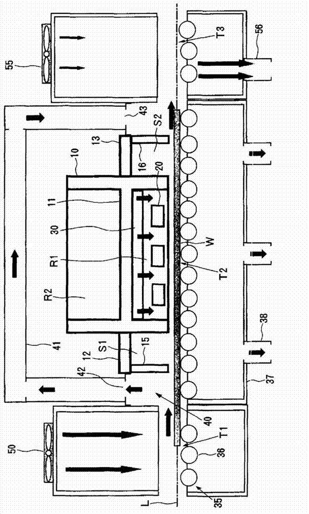
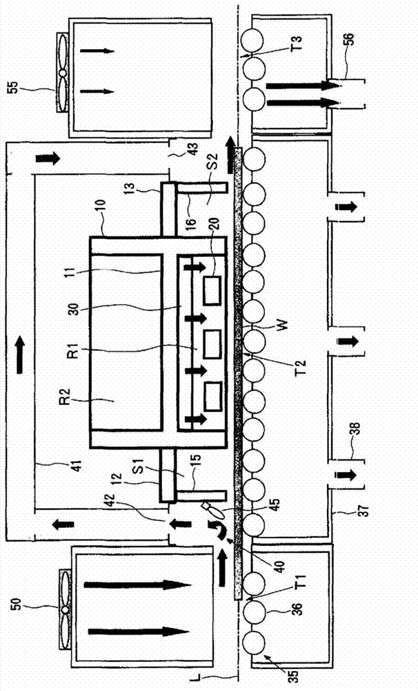
[0061] figure 1 It is an explanatory sectional view showing the structure of an example of the light irradiation device of the present invention. The light irradiation device pairs along the horizontal direction ( figure 1 One side of the substrate W conveyed by the substrate conveying path L extending in the left and right direction ( figure 1 (middle is the upper surface) is irradiated with ultraviolet rays with a wavelength of 200 nm or less, has an opening for light emission formed on the lower surface, and has a substantially rectangular parallelepiped shape. The lamp housing 10 is provided with a partition wall 11 that partitions the interior of the lamp housing 10 up and down, thereby forming a lamp housing room R1 below the housing wall 11 and forming an electrical component housing room R2 above the housing wall 11 .

[0062] In the lamp housing room R1 ...


PUM


Abstract

A light irradiation apparatus is provided and restricts the air to flow between a processed object substrate and a lamp, so that light can irradiate the processed object substrate in high efficiency. The light irradiation apparatus is provided with a chimney, an excimer lamp irradiating light to one surface of the processed object substrate transmitted along a substrate transmission path arranged in the chimney, and a gas supply unit for supplying inert gases between the processed object substrate and the excimer lamp. On an upper side of the chimney of the substrate transmission path, a pressure buffer space is formed near the chimney. The light irradiation apparatus is characterized in that an air exhaust unit is disposed on the upper side of the pressure buffer space of the substrate transmission path and is used for exhausting the air flowing along a surface irradiated by the light.

Description

technical field [0001] The present invention relates to a light irradiation device for irradiating a substrate to be processed transported along a substrate transport path with light. Background technique [0002] For example, in a manufacturing process of a liquid crystal display device or the like, in order to form a thin film with high adhesion to a substrate such as a glass substrate, the surface of the substrate is irradiated with ultraviolet rays to clean the glass substrate. [0003] In the light irradiation device used in the cleaning process of such a substrate, it is required that the light irradiation process can be continuously performed on a large number of substrates. As such a light irradiation device, there is known a device that irradiates light to a substrate transported along a substrate transport path. . [0004] image 3 It is an explanatory cross-sectional view showing the structure of an example of a conventional light irradiation device that irradiat...

Claims


Application Information

Patent Timeline
Patent Type & Authority Applications(China)
IPC IPC(8): B08B7/00B08B5/02
CPCB08B5/02B08B7/0035G02F1/13G02F1/1316
Inventor 山森贤治纳田诚人中岛幸秀小柳博
Owner USHIO DENKI KK
Why Eureka
Try Eureka