Blanking device for full-automatic shaft servo manipulator

A blanking device and fully automatic technology, applied in the field of machinery, can solve problems such as improper protection of bars, increased frequency of changing troughs, increased production costs, etc., to achieve convenient operation, avoid bar damage, and protect from damage Effect

Active Publication Date: 2013-06-05
宁波宫铁智能科技有限公司
View PDF10 Cites 18 Cited by
  • Summary
  • Abstract
  • Description
  • Claims
  • Application Information

AI Technical Summary

Problems solved by technology

[0002] As a relatively common industrial material, bar is widely used in various industries. However, in the process of processing the existing assembly line automatic machine tools, the protection of the bar is often improper due to the imperfect blanking device. The material is damaged, or the production efficiency is reduced due to the frequent replacement of the material box due to too little material in the material box; most of the blanking devices of the existing machine tools are directly installed at the discharge end of the machine tool with a downward slope, consisting of a bottom plate and two side plates The blanking chute composed of the blanking chute extends into the storage bin set below it or hangs above the storage bin
[0003] However, these two blanking methods have different defects in actual use; when the blanking chute extends into the storage silo, the height of the notch of the blanking chute from the bottom of the storage silo is less than the height of the wall of the storage silo. In this way, during the process of continuously accumulating bars in the storage bin, the bars in the storage bin are piled up higher and higher until they are piled up at the notch of the blanking groove. At this time, the bars cannot slide down into the storage bin. It can only stay on the blanking chute, so that the original storage bin space cannot be fully utilized, making the actual storage volume of the storage bin far lower than the theoretical storage volume, resulting in an increase in the number of replacement chute, and low production efficiency In some cases, the working intensity of the staff is also relatively heavy, and the orderly production cannot be guaranteed; and when the blanking chute is suspended above the storage bin, the vertical height between the blanking chute and the bottom surface of the storage bin is bound to be increased, and the bar The inertia of the material increases during the falling process, and the impact force when the bar material is in contact with the storage bin is also increased, which will cause damage and incompleteness of the bar material to a certain extent, resulting in greater consumption of raw materials and poor production quality. Not guaranteed, production cost increases

Method used


Image

  • Blanking device for full-automatic shaft servo manipulator
  • Blanking device for full-automatic shaft servo manipulator
  • Blanking device for full-automatic shaft servo manipulator

Examples


Embodiment Construction

[0021] The following are specific embodiments of the present invention and in conjunction with the accompanying drawings, the technical solutions of the present invention are further described, but the present invention is not limited to these embodiments.

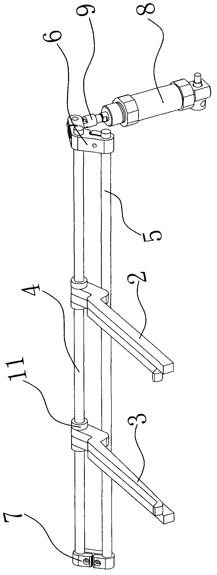
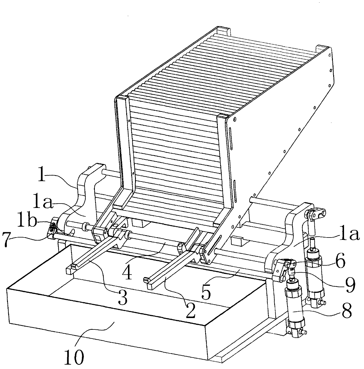
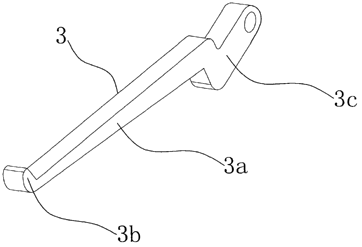
[0022] Such as Figure 1 to Figure 4 As shown, the blanking device of the shaft-type automatic servo manipulator is set on the frame 1, including the rotating shaft, the drive mechanism for controlling the circumferential rotation of the rotating shaft, and two sets of parallel blanking assemblies, and a useful one is placed under the blanking assembly. For the storage bin 10 containing processed bars, the rotating shaft includes a first rotating shaft 4 and a second rotating shaft 5 arranged in parallel, wherein the second rotating shaft 5 is located in front of the first rotating shaft 4 .

[0023] Two parallel vertical plates 1a are erected on the frame 1, and the two ends of the first rotating shaft 4 traverse the two ...


PUM


Abstract

The invention discloses a blanking device, belongs to the technical field of machinery, and solves the technical problems that a blanking device of a traditional machine tool easily breaks and damages rod materials in blanking, and the number of the rod materials stored in a storage bin once is small as the space of the storage bin for storing the rod materials cannot be sufficiently used. The technical scheme includes that the blanking device comprises a frame, a rotation shaft, a driving mechanism and a blanking component, the rotation shaft is mounted on the frame, the blanking component comprises a material guide rod and a material receiving shifter, the material guide rod and the material receiving shifter are mounted on the rotation shaft, a material limit portion is formed at the front end of the material receiving shifter, the top end of the material limit portion is higher than the upper surface of the material guide rod, and the height between the top end of the material limit portion and the lower surface of the material receiving shifter is smaller than or equal to the thickness of the material guide rod. The blanking device has the advantages that the rod materials are prevented from being damaged in the blanking process, integrity of the rod materials is ensured, the space of the storage bin is sufficiently used, the rod materials are furthest stored in the storage bin, transfer frequency is decreased, and production efficiency is improved.

Description

technical field [0001] The invention belongs to the technical field of machinery, and in particular relates to a blanking device for a fully automatic servo manipulator of shafts. Background technique [0002] As a relatively common industrial material, bar is widely used in various industries. However, in the process of processing the existing assembly line automatic machine tools, the protection of the bar is often improper due to the imperfect blanking device. The material is damaged, or the production efficiency is reduced due to the frequent replacement of the material box due to too little material in the material box; most of the blanking devices of the existing machine tools are directly installed at the discharge end of the machine tool with a downward slope, consisting of a bottom plate and two side plates The blanking chute formed, the blanking chute extends into the storage bin arranged below it or hangs above the storage bin. [0003] However, these two blankin...

Claims


Application Information

Patent Timeline
Patent Type & Authority Applications(China)
IPC IPC(8): B23Q7/00B23Q7/04
Inventor 朱建群
Owner 宁波宫铁智能科技有限公司
Why Eureka
Try Eureka