Solar heat transfer system (HTPL), high temperature pressurized loop

a heat transfer system and solar energy technology, applied in solar heat systems, solar heat collector safety, lighting and heating apparatus, etc., can solve the problems of low collector efficiency and small loss to pay for a system using significantly less material, and achieve the effect of more corrosive materials

Inactive Publication Date: 2011-03-29
BUTLER BARRY LYNN
View PDF13 Cites 15 Cited by
  • Summary
  • Abstract
  • Description
  • Claims
  • Application Information

AI Technical Summary

Benefits of technology

[0005]In summary, the present invention is a closed fluid loop solar system which is unpressurized when cold and upon heating becomes self-pressurized by fluid thermal expansion. The pressure is limited by a pressure relief valve which allows trapped gas and fluid to leave the closed-loop system and go to the overflow reservoir. Upon cool down the vacuum caused by fluid thermal contraction draws fluid back into the system from the overflow reservoir through a slightly sub-atmospheric vacuum relief valve. The normal daily heating and cooling cycles keeps the system full of fluid by automatically eliminating non-condensable gases such as air. The sola...

Problems solved by technology

The higher fluid temperature in the collector will lower the collectors' efficiency, since it is losi...

Method used


Image

  • Solar heat transfer system (HTPL), high temperature pressurized loop
  • Solar heat transfer system (HTPL), high temperature pressurized loop
  • Solar heat transfer system (HTPL), high temperature pressurized loop

Examples


Embodiment Construction

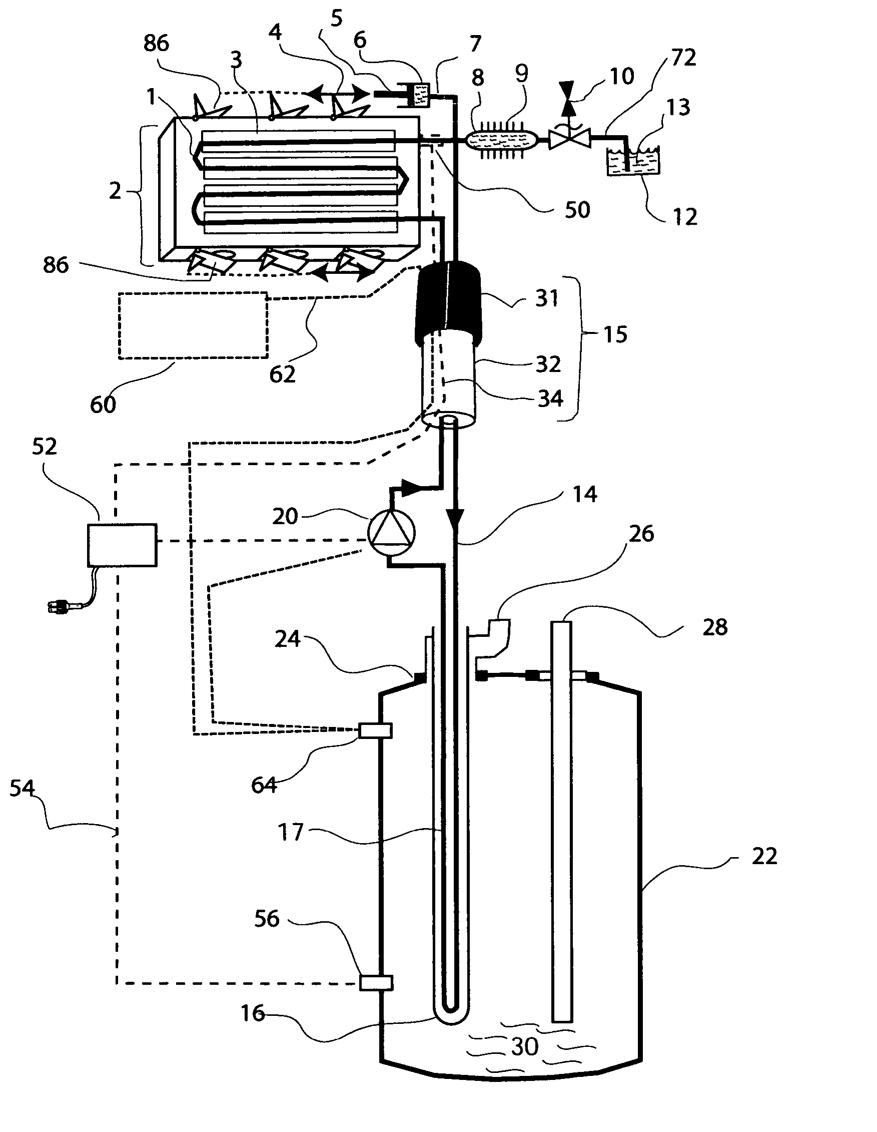
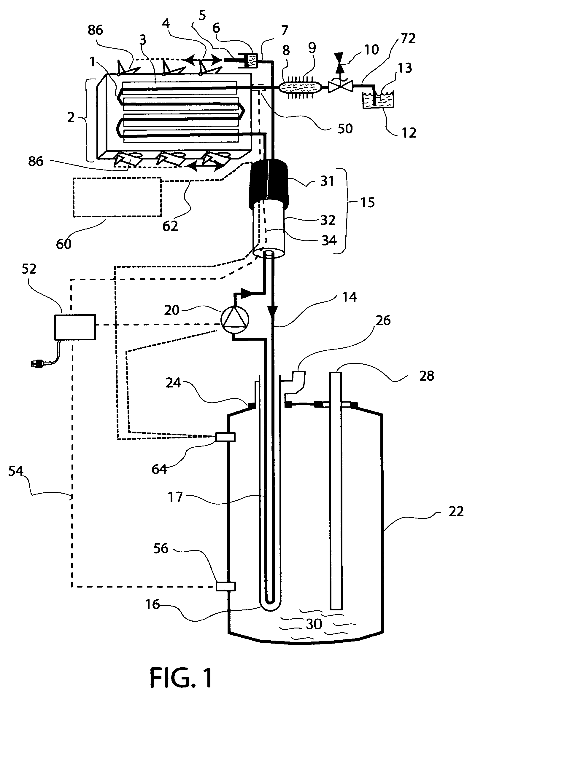
[0018]The invention (FIG. 1) consists of a pressurized heat transfer loop (1, 14&17) which operates above the boiling point of water at one atmosphere of pressure, 212° Fahrenheit. The heat transfer fluid (13) is heated, in the solar collector tube (1) by the sun. The solar collector (2) can be single, or double glazed. The heated fluid then exits the solar collector in tube (1) and comes to a three-way connection. Path one (7) goes to the pressure actuator (6), which can move the actuator arm (5) to actuate air dampers with motion (4). Path one may not be needed if the path two pressurized fluid / steam-to-air radiator is sufficient to prevent overheating. Path two goes through a pressurized radiator (8) with fins (9) to a pressure relief valve (10) which includes a vacuum recovery valve to let expelled heat exchanger fluid (13) back into the system from the fluid overflow / recovery reservoir (12), while excluding non-condensable air. Path three (14) is the fluid tubing leading to the...


PUM


Abstract

Delivering heat from modem high temperature solar collectors to hot water storage tanks is more effectively done using unpressurized when cold, self-pressurized on heat up, automatic air eliminating, higher temperature fluid loops. A pressurizing valve, an overflow reservoir and a vacuum relief valve are used. Non-toxic water/antifreeze mixtures are pressurized up to about two atmospheres resulting in a 265° Fahrenheit boiling point. Loss of circulation under full sun results in solar collector boiling under pressure. The steam generated in the solar collector is condensed in the pressurized liquid-to-air radiator, a steam heat pipe, and water is returned to the solar collector to keep it completely full of fluid and steam. A set of pressure-actuated air dampers on the solar collector can also be used to shed the excess solar collector heat.

Description

BACKGROUND OF INVENTION[0001]This invention pertains to the collection and the delivery of heat from a roof or a ground mounted solar collector panel to a hot water storage tank via the use of a self-pressurized, high temperature fluid-filled loop, which eliminates non-condensable gases, such as air, from the fluid loop. The pressurized loop system utilizes a mixture of water and antifreeze or another suitable fluid is circulated via a pump. In addition, the system is self-protected from over-temperature and over-pressure if the circulating pump fails. The higher temperature, compared to an unpressurized, fluid heat transfer loop allows for a smaller heat transfer area and hence a more compact hot water tank heat exchanger, and a small diameter (approximately two inch), flexible, insulated umbilical which contains both electrical and fluid tubing connections (approximately ¼ inch outside diameter tubing) to go both out and back from the hot water tank to the solar collector for ease...

Claims


Application Information

Patent Timeline
IPC IPC(8): F24J2/40F24J2/46
CPCF24J2/4627F24J2/4649Y02E10/40F24S80/20F24S40/53
Inventor BUTLER, BARRY LYNN
Owner BUTLER BARRY LYNN
Why Eureka
Try Eureka