Automatic brake apparatus for mistaken stepping on accelerators

A technology of automatic braking and accidental stepping on the accelerator, which is applied in the field of auto parts, can solve the problems of complex structure and principle, interference of electronic system, etc., and achieve the effect of simple device structure, convenient modification, and easy installation and use

Inactive Publication Date: 2013-06-05
管兆康
View PDF8 Cites 8 Cited by
  • Summary
  • Abstract
  • Description
  • Claims
  • Application Information

AI Technical Summary

Problems solved by technology

[0003] The technical problem to be solved by the present invention is to propose an automatic brake for mistakenly stepping on the accelerator with simple structure, safe and reliable, and easy to install and use in view of the complex structure and principle of the existing system for preventing mistakenly stepping on the accelerator. device

Method used


Image

  • Automatic brake apparatus for mistaken stepping on accelerators
  • Automatic brake apparatus for mistaken stepping on accelerators

Examples


Embodiment 1

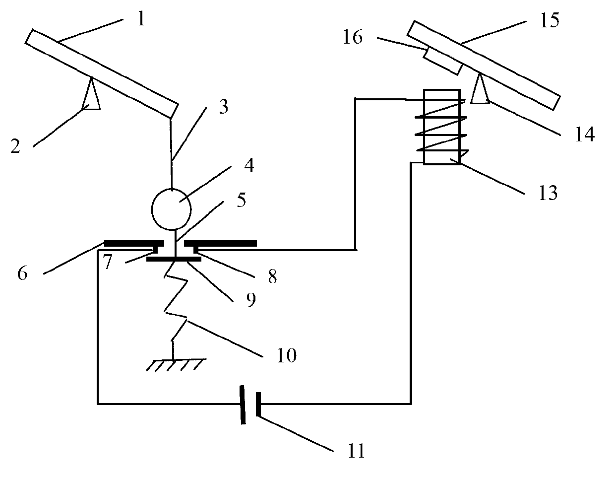
[0029] The automatic braking device of stepping on the accelerator by mistake of the present embodiment, as figure 1 Shown, it comprises accelerator pedal 1, brake pedal 15 and braking device, and gas pedal support point 2 and brake pedal support point 14 are set at the lower middle position of accelerator pedal 1 and brake pedal 15 respectively. The braking device includes a two-point retractor 4 and an electromagnet circuit. The upper end of the two-point retractor 4 is connected to the rear end of the accelerator pedal 1 through the retractor webbing I3, and the two-point retractor 4 The lower end of the retractor ribbon II5 is fixed on the limit lower baffle 9, the bottom of the limit lower baffle 9 is connected to one end of the spring 10, the other end of the spring 10 is fixed, and the two-point retractor 4 is connected to the limit The limit upper baffle 6 is set between the lower baffle 9, and the limit upper baffle 6 is provided with a switch contact I7 and a switch ...

Embodiment 2

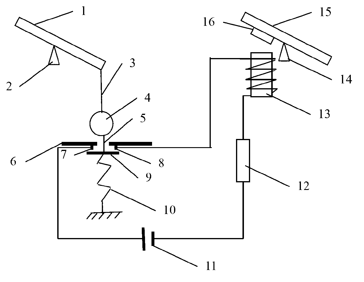
[0033] The automatic braking device of stepping on the accelerator by mistake of the present embodiment, as figure 2 As shown, it includes an accelerator pedal 1, a brake pedal 15 and a brake device, and an accelerator pedal support point 2 and a brake pedal support point are respectively set at the position of the rear end 1 / 3 of the full length below the accelerator pedal 1 and the brake pedal 15. 14. The braking device includes a two-point retractor 4 and an electromagnet circuit, one end of the retractor webbing I3 is connected to the rear end of the accelerator pedal 1, and the other end of the retractor webbing I3 is fixed on the limit lower baffle 9 above, the upper end of the two-point retractor 4 is fixed below the limit lower baffle 9 through the retractor ribbon II5, and the lower end of the two-point retractor 4 is connected to one end of the spring 10 through the retractor ribbon III17 , the other end of the spring 10 is fixed, a limit upper baffle 6 is set betw...


PUM


Abstract

The invention discloses an automatic brake apparatus for mistaken stepping on accelerators. The apparatus comprises an accelerator pedal, a brake pedal and a brake gear. The brake gear comprises a two-point retractor and an electromagnetic circuit. The upper end of the two-point retractor is connected to the rear end of the accelerator pedal, the lower end of the two-point retractor is fixed on the upper portion of a lower limit baffle through a retractor braid, and the lower portion of the lower limit baffle is connected with a spring fixed at the end. An upper limit baffle is arranged between the two-point retractor and the lower limit baffle, and switch contacts mutually separated in the electromagnetic circuit are arranged on the upper limit baffle and movably connected with the lower limit baffle. The upper portion of an electromagnet right aligns to the brake pedal. When an accelerator is stepped fiercely, a high acceleration enables the two-point retractor to be retracted tightly, the lower limit baffle moves upwards to close the electromagnetic circuit, and accordingly, the brake pedal is forced to be pulled downwards rapidly through strong electromagnet absorption force to achieve emergency braking. The automatic brake apparatus is simple in structure, safe and reliable and convenient to mount and use.

Description

technical field [0001] The invention belongs to the technical field of auto parts and relates to a brake device, in particular to an automatic brake device for mistakenly stepping on the gas pedal. Background technique [0002] Generally, when a skilled driver encounters an emergency, the right foot that steps on the gas pedal "without thinking about it" "just unconsciously" moves to the left and steps on the brake, which is a natural instinctive reaction. The novice has not yet formed this kind of reaction. When encountering an emergency, he will panic and step on his right foot without moving. In recent years, with the great improvement of people's material life, the number of private cars has increased sharply, and the number of "road killers" has continued to increase. Among the traffic accidents that have occurred, many of them are in emergency situations. The gas pedal is produced when the brake is pressed. In order to prevent such traffic accidents, it is necessary ...

Claims


Application Information

Patent Timeline
Patent Type & Authority Applications(China)
IPC IPC(8): B60T7/12
Inventor 管兆康
Owner 管兆康
Why Eureka
Try Eureka