Modified clamping piece type anchorage device

A clip-type, anchorage technology, applied in the direction of construction, sheet pile walls, foundation structure engineering, etc., can solve the problems of waste of materials, construction obstacles of adjacent buildings, difficult to recycle, etc., to achieve a simple recycling method and convenient recycling of cores materials, easy implementation

Active Publication Date: 2013-06-05
SUZHOU NG FOUND ENG
View PDF6 Cites 26 Cited by
  • Summary
  • Abstract
  • Description
  • Claims
  • Application Information

AI Technical Summary

Problems solved by technology

[0003] In the prior art, cast-in-situ piles, anchor rods and soil nails are widely used in geotechnical engineering, and the core material raw materials of the main force-bearing components are all steel materials, such as steel bars, steel pipes, steel strands, and steel wire ropes, which are used to reinforce foundations. The pits and slopes have achieved very good results, but the steel materials used are usually used for one-time use, and the core materials are left in the soil layer after use, which not only wastes materials, but also forms obstacles to the construction of adjacent buildings
For example, the length of the commonly used anchor rods basically reaches 20-30 meters, and the soil nails reach 8-15 meters. It is difficult to recycle them according to the existing technology.
In quite a few engineering examples, special construction measures have to be taken in the subsequent construction of adjacent buildings due to the impact of anchor rods and soil nails, which greatly increases the difficulty and cost of dealing with underground obstacles during development.

Method used


Image

  • Modified clamping piece type anchorage device
  • Modified clamping piece type anchorage device

Examples


Embodiment Construction

[0015] The present invention is described below in conjunction with accompanying drawing.

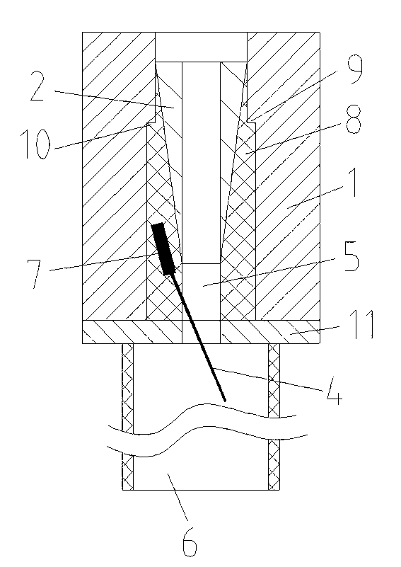
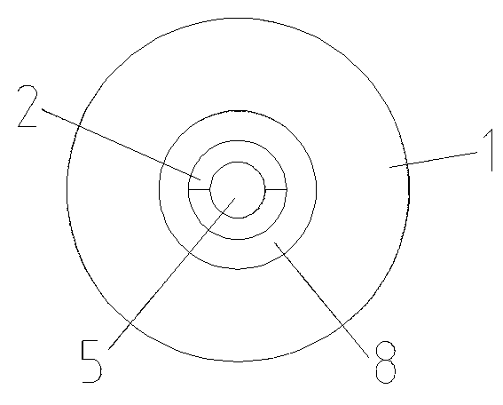
[0016] as attached Figure 1-2 Shown is the improved clip-type anchor of the present invention, which includes an anchor ring assembly 1, a clip assembly 2, a sheath 8, and an isolation sleeve 6; the anchor ring assembly 1 is provided with an anchor hole 5; the The anchor ring assembly 1 includes an anchor ring body (not marked) and a steel plate 11; the steel plate 11 is arranged at the bottom of the anchor ring body; the anchor hole 5 passes through the anchor ring body and the steel plate 11; the anchor ring body The first boss 9 is arranged in the anchor hole on the top; the first boss 9, the steel plate 11, and the anchor hole on the anchor ring body form an enlarged part; the upper part of the sheath 8 is provided with a second boss, When the sheath 8 is inserted into the enlarged part, the bottom of the sheath 8 is arranged on the steel plate 11, and the second boss 10 cooperate...


PUM


Abstract

The invention discloses a modified clamping piece type anchorage device which comprises an anchor ring assembly, a clamping piece assembly, a jacket and an isolation sleeve tube, wherein an anchor eye is formed in the anchor ring assembly, an expansion portion is arranged in the anchor eye, the jacket is arranged in the anchor eye, when the clamping piece assembly is inserted into the anchor eye, the jacket is clamped in the anchor eye through the anchor ring assembly and the clamping piece assembly, the isolation sleeve tube is arranged at the end portion of the anchor ring assembly, an electric heating device is arranged on the jacket, and the jacket is made from fusible materials. The modified clamping piece type anchorage device can bear the drawing force of 28 tons in the process of support of a foundation pit and a slope and can fully meet existing support requirements. In addition, when the modified clamping piece type anchorage device is needed to be recycled, the electric heating device can be powered on through a line and heat, the jacket can be softened or melted, friction resistance between core materials and the clamping piece assembly can be reduced, and therefore the purpose of convenient recovery of the core materials is achieved. The modified clamping piece type anchorage device is simple in scheme, practical, simple in recovery method of the core materials and convenient to operate.

Description

technical field [0001] The invention relates to an improved clip-type anchorage which can realize large-tonnage drawing and facilitate the recovery of core materials, which is applied in foundation pit and side slope support of geotechnical engineering. Background technique [0002] With the advancement of urbanization, the construction of underground facilities such as underground parking lots, underground pedestrian passages, underground commercial streets, and underground railways requires foundation pit and slope support. [0003] In the prior art, cast-in-situ piles, anchor rods and soil nails are widely used in geotechnical engineering. The core material of the main force-bearing components is steel, such as steel bars, steel pipes, steel strands, and steel wire ropes. The pits and slopes have achieved very good results, but the steel materials usually used are one-time use, and the core materials are left in the soil layer after use, which not only wastes materials, b...

Claims


Application Information

Patent Timeline
Patent Type & Authority Applications(China)
IPC IPC(8): E02D5/74E02D5/76E02D9/00
CPCE02D5/76E02D9/00E02D5/74
Inventor 周建明陆晓明徐高巍
Owner SUZHOU NG FOUND ENG
Why Eureka
Try Eureka