Rapid disconnection control circuit applied to power management circuit

A technology of power management and electrical control, which is applied in the direction of control/regulation system, adjustment of electrical variables, instruments, etc. It can solve problems such as hardware system error, circuit instability state, and low circuit current, so as to avoid logic function or storage error Effect

Inactive Publication Date: 2014-11-05
SHANDONG UNIV
View PDF5 Cites 0 Cited by
  • Summary
  • Abstract
  • Description
  • Claims
  • Application Information

AI Technical Summary

Problems solved by technology

However, in some cases, during the power-off process of the chip, due to the low current consumption of the circuit and the large voltage stabilizing capacitor at the power supply voltage terminal, the power supply voltage will drop very slowly, such as figure 1 shown in
As a result, during the power-off process of the power supply voltage, because the power supply voltage is already lower than the normal working voltage of the circuit, but it is not 0, some circuits will appear unstable, causing the hardware system to issue wrong instructions or execute wrong operation
Especially in application environments such as non-contact smart cards, the power supply voltage is maintained by the charge stored on the capacitor in the chip, and the power-off process will be very slow, which may easily cause logic function or storage errors of the chip during power-off

Method used


Image

  • Rapid disconnection control circuit applied to power management circuit
  • Rapid disconnection control circuit applied to power management circuit
  • Rapid disconnection control circuit applied to power management circuit

Examples


Embodiment 1

[0019] The invention is applied to a low-dropout linear voltage stabilizing circuit LDO to realize fast power-off.

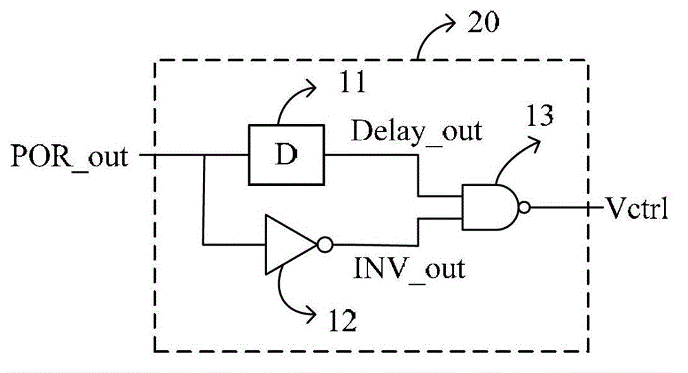
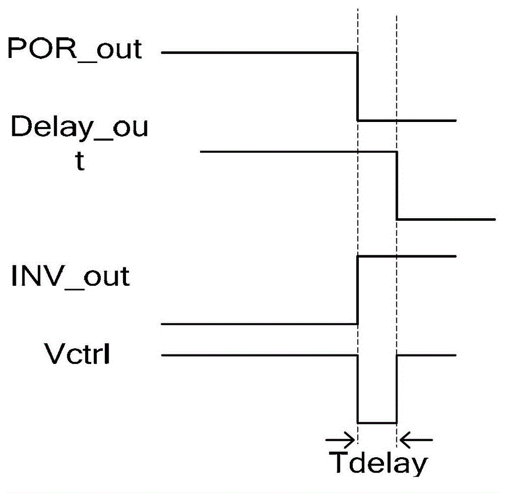
[0020] Such as figure 2 As shown in 4, a fast power-off control circuit 10 used in a power management circuit includes a POR falling edge detection circuit 20 and a PMOS discharge tube Mp2. The POR falling edge detection circuit 20 includes a delay module 11, an inverter The phase converter 12 and the NAND gate 13, the input terminal of the POR falling edge detection circuit 20 is connected to the input terminal of the delay module 11 and the input terminal of the inverter 12, and the output terminal (Delay_out) of the delay module 11 is connected to the inverter 12 The output terminal (INV_out) of the phaser 12 is connected to the two input terminals of the NAND gate 13, and the output terminal (Vctrl) of the POR falling edge detection circuit 20 is connected to the output terminal of the NAND gate 13; the POR falling edge detection circuit 20 The output terminal...


PUM


Abstract

The invention relates to a rapid disconnection control circuit applied to a power management circuit. The rapid disconnection control circuit applied to the power management circuit comprises a power on reset (POR) falling edge detection circuit and a p-channel metal oxide semiconductor (PMOS) discharge tube Mp2, the POR falling edge detection circuit comprises a delay module, a phase inverter and an NAND gate, the input end of the POR falling edge detection circuit is connected with the input end of the delay module and the input end of the phase inverter, the output end of the delay module and the output end of the phase inverter are respectively connected with two input ends of the NAND gate, the output end of the POR falling edge detection circuit is connected with the output end of the NAND gate, the output end of the POR falling edge detection circuit is connected with a grid electrode of the PMOS discharge tube Mp2, a source electrode of the MPOS discharge tube Mp2 is connected with supply voltage Vdd, and a drain electrode of the PMOS discharge tube Mp2 is connected with the ground. When the rapid disconnection control circuit is applied to the power management circuit, the rapid disconnection control circuit guarantees that a hardware system is powered off in time in a disconnection process of the supply voltage, and avoids that the hardware system sends wrong instructions or executes wrong operation due to unstable states of parts of circuits under the condition of low voltage.

Description

Technical field [0001] The invention relates to a fast power-off control circuit applied in a power management circuit, and belongs to the technical field of power management control circuits. Background technique [0002] With the increasing role of power management circuits in electronic products, the performance of power circuits in electronic products is becoming more and more important. The power management circuit is used on almost every chip, which requires the power management circuit to have high indicators to extend the use time of electronic products. For example, Low Drop Voltage Regulator (LDO) is a commonly used power management circuit. A common LDO is often connected with a capacitor of a few microfarads to ensure stable operation of the circuit. However, in some cases, during the chip power-off process, due to the low current consumption of the circuit and the large voltage stabilizing capacitor at the power supply voltage terminal, the power supply voltage will...

Claims


Application Information

Patent Timeline
Patent Type & Authority Patents(China)
IPC IPC(8): G05F1/56
Inventor 周莉潘芦苇孙涛陈鹏高园园
Owner SHANDONG UNIV
Why Eureka
Try Eureka