Back plate wall built-up structure of electronic system
An electronic system and wall structure technology, applied in the direction of electrical digital data processing, digital processing power distribution, instruments, etc., can solve the problems of labor-intensive and inconvenient, cost-intensive, maintenance personnel spending more time and manpower, etc.
- Summary
- Abstract
- Description
- Claims
- Application Information
AI Technical Summary
Problems solved by technology
Method used
Image

Examples
Embodiment Construction
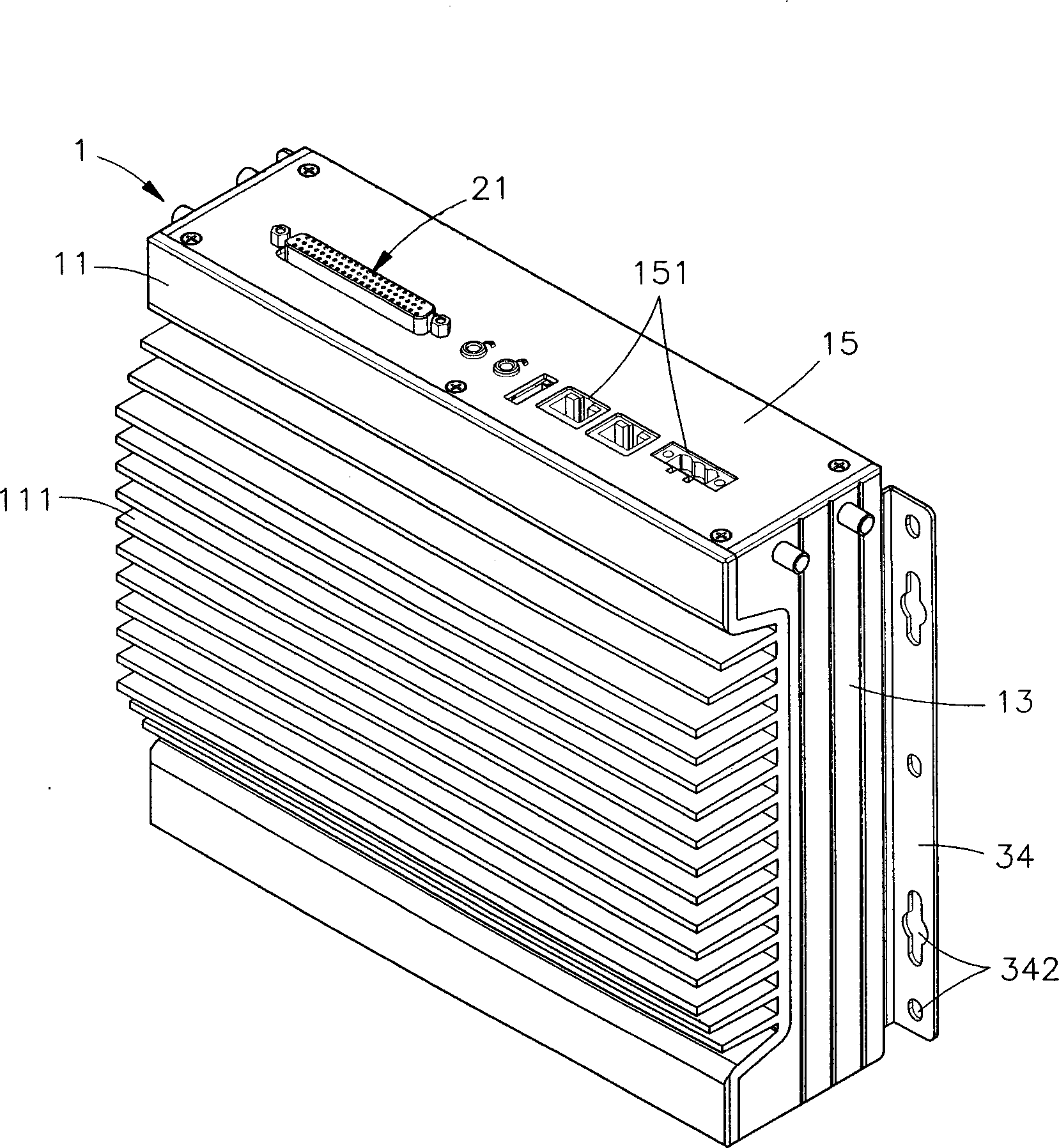
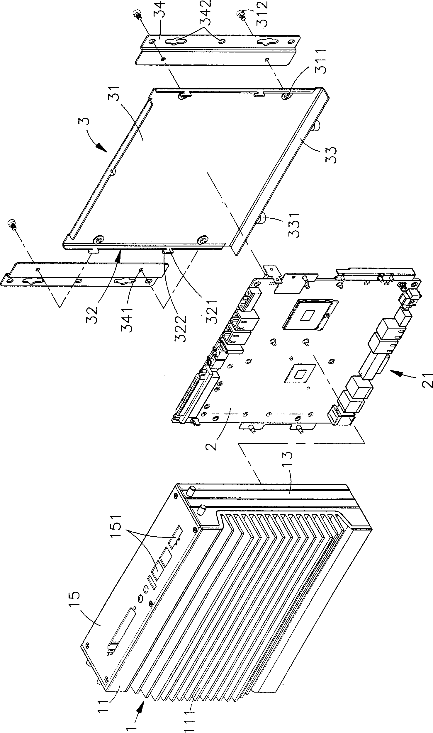
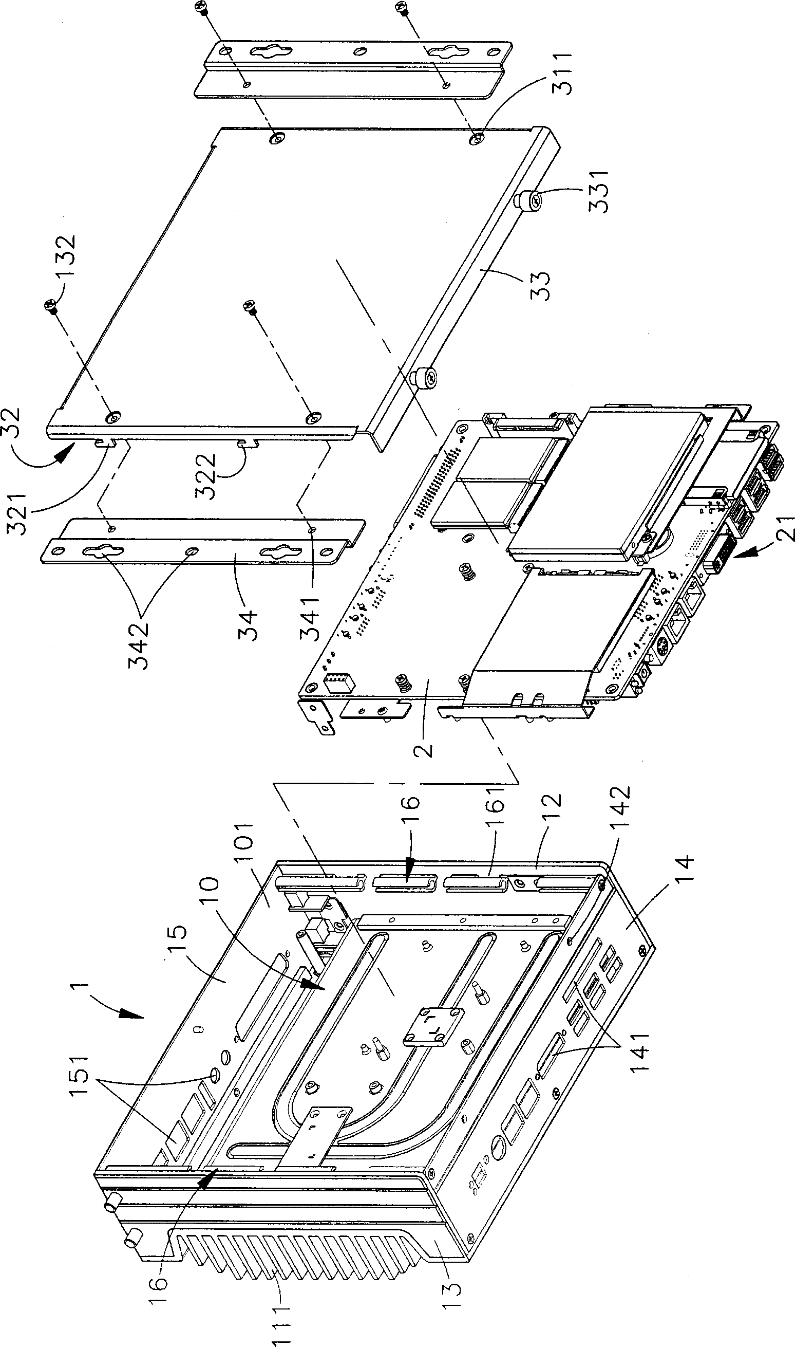
[0018] see figure 1 , figure 2 , image 3 As shown, they are respectively a three-dimensional appearance view, a three-dimensional exploded view and a three-dimensional exploded view from another perspective of the present invention. It can be clearly seen from the figure that the present invention includes an organic casing 1, a circuit board 2 and a back cover 3. , so the main components and features of this case are described in detail below, among which:
[0019] The casing 1 has a front casing 11, and opposite casing casings 12, 13 are provided on both sides of the front casing 11 in the same direction, and the upper and lower sides of the two casing casings 12, 13 face the front casing. The opposite bottom shell 14 and upper cover 15 are provided extending in the direction of the body 11, thereby forming an accommodating space 10 with an opening 101 inside the shell 1; in addition, the two outer shells 12, 13 of the shell 1 are opposite A sliding portion 16 is dispo...
PUM
 Abstract
Description
Claims
Application Information
 - R&D
- Intellectual Property
- Life Sciences
- Materials
- Tech Scout
- Unparalleled Data Quality
- Higher Quality Content
- 60% Fewer Hallucinations
Browse by: Latest US Patents, China's latest patents, Technical Efficacy Thesaurus, Application Domain, Technology Topic, Popular Technical Reports.
© 2025 PatSnap. All rights reserved.Legal|Privacy policy|Modern Slavery Act Transparency Statement|Sitemap|About US| Contact US: help@patsnap.com