
Converter which is designed to be used on motor vehicle and provides electric propulsive force circuit

A technology of motor vehicles and electric propulsion, applied in the field of converters, can solve problems such as loss and achieve the effect of reducing volume

Active Publication Date: 2013-06-05
VALEO SYST DE CONTROLE MOTEUR
View PDF3 Cites 1 Cited by
  • Summary
  • Abstract
  • Description
  • Claims
  • Application Information

AI Technical Summary

Problems solved by technology

[0023] The problem is that these materials have a high level of loss at high frequencies due to the modulation of the flux generated by these high frequencies

Method used


Image

  • Converter which is designed to be used on motor vehicle and provides electric propulsive force circuit
  • Converter which is designed to be used on motor vehicle and provides electric propulsive force circuit
  • Converter which is designed to be used on motor vehicle and provides electric propulsive force circuit

Examples


Embodiment Construction

[0056] Structurally and functionally identical elements appearing in different figures have the same reference numerals, unless specifically stated otherwise

[0057] Figure 9 A magnetic circuit 900 according to the invention is shown, i.e. comprising two units 901 or 903 equipped with respective inductive elements 902 and 904 (represented by coils), which are coupled so as to be controllable alternately according to the following modes:

[0058] - According to the common mode, wherein the apparent inductance of said magnetic circuit 900 is relatively high, eg of the order of the sum of the inductances LA and LB specific to each of said inductive elements 902 and 904 . With such a high apparent inductance, the reversal of magnetic flux in the circuit is limited (described in detail below), which reduces core losses.

[0059] - According to the differential mode, wherein the apparent inductance of the magnetic circuit is relatively low, eg of the order of the leakage inductan...


PUM


Abstract

The invention relates to a circuit (900, 900') which is designed to be used on a motor vehicle and provides electric propulsive force. A power supply of the electric propulsive force transmitted by a battery of the vehicle to the circuit (900, 900') acquires at least two units (901 and 903; and 901' and 903'). The circuit (900, 900') comprises inductance elements (902 and 904; and 902' and 904') and a current transistor which is connected to the inductance elements (902 and 904; and 902' and 904') and manages the inductance elements (902 and 904; and 902' and 904'). The circuit (900, 900') is characterized in that the inductance elements (902 and 904; and 902' and 904') are coupled to form a magnetic circuit (1400) capable of being alternately controlled according to the following modes: a common mode, wherein apparent inductance of the magnetic circuit (1400) is provided with a summational order of specific inductance of each inductance element, or a difference mode, wherein the apparent inductance of the magnetic circuit (1400) is provided with an order of coupled leakage inductance between coupled inductance elements.

Description

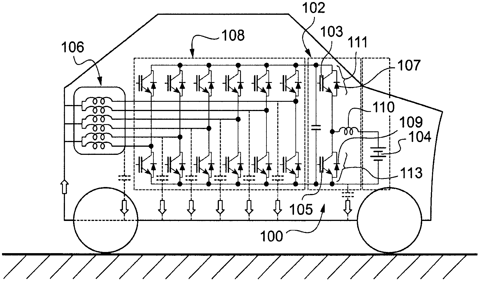
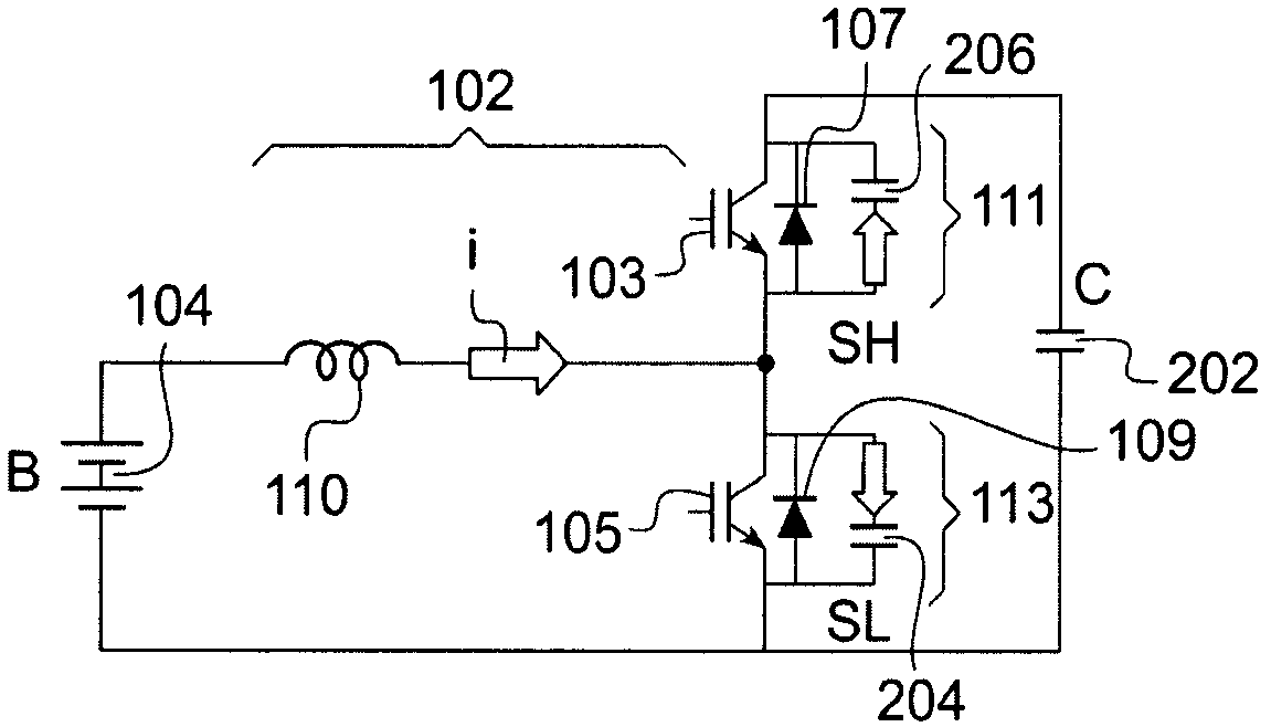
technical field [0001] The invention relates to converters designed for circuits providing electric propulsion in motor vehicles. Background technique [0002] see figure 1 It is known practice to equip a fully or partially electrically propelled vehicle 100 with a power converter 102 capable of boosting the voltage of a battery 104 to provide power to a generator 106 (typically via an inverter 108 ). [0003] Since the working power in such a converter 102 is typically between 20 and 100 kW, it is worthwhile to manufacture a multi-unit converter in which the supply current originating from the battery 104 is distributed among several conversion units. [0004] Using such multi-cell converters faces the problem of being too costly because of the amount of silicon required for the switches 111 and 113 used in the cells, and their transistors 103 or 105 and their diodes 107 or 109 are also costly. [0005] In the case of electric vehicles, especially hybrid vehicles, the vol...

Claims


Application Information

Patent Timeline
Patent Type & Authority Applications(China)
IPC IPC(8): H02M3/07
Inventor L·德索萨M·福尔S·方泰尼
Owner VALEO SYST DE CONTROLE MOTEUR
Learn More