Motor control apparatus

A technology of motor control and feedback control, applied in motor control, AC motor control, electrical program control, etc., can solve problems such as inability to perform open-loop control operations and inability to set reference positions for open-loop control operations

Active Publication Date: 2013-06-05
DENSO CORP
View PDF8 Cites 16 Cited by
  • Summary
  • Abstract
  • Description
  • Claims
  • Application Information

AI Technical Summary

Problems solved by technology

Thus, when the output shaft sensor is removed, it is not possible to set the reference positi

Method used


Image

  • Motor control apparatus
  • Motor control apparatus
  • Motor control apparatus

Examples


Embodiment Construction

[0024] A gear shift device of an automatic transmission according to an embodiment of the present disclosure will be described.

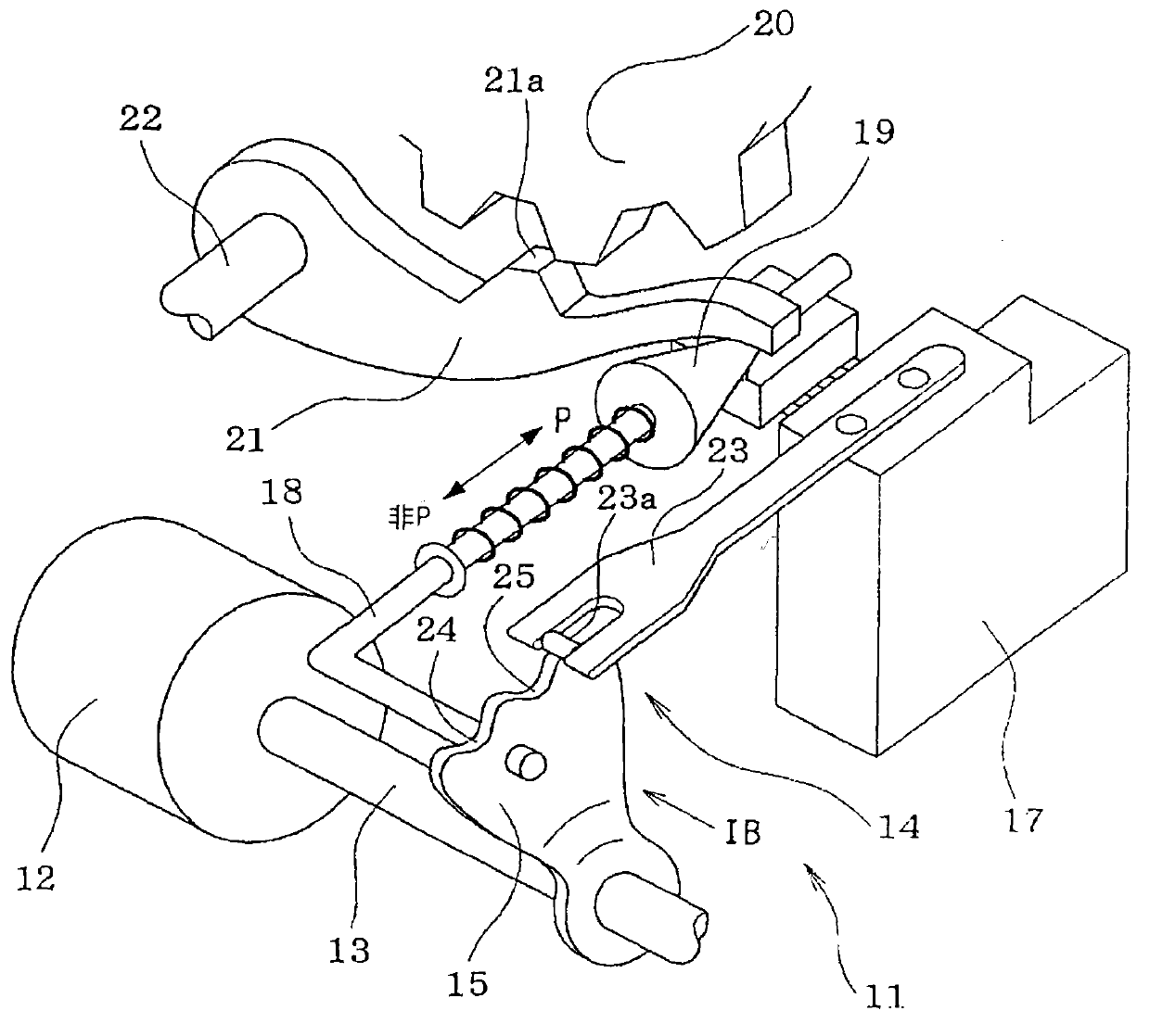
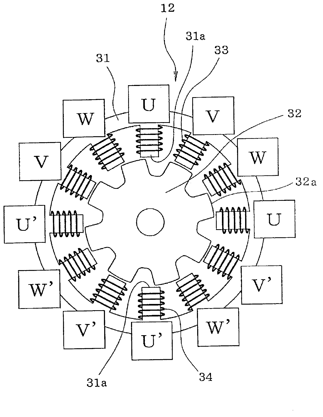
[0025] First, refer to Figure 1A and 1B The structure of the gear shift mechanism 11 is schematically described. The motor 12 serving as the drive source of the range switching mechanism 11 may be, for example, a switched reluctance (SR) motor. The motor 12 includes a speed reduction mechanism 26 that reduces the rotational speed of the rotor 32 of the motor 12 (see Figure 4 ). A brake 15 is fixed to the output shaft 13 of the motor 12 .

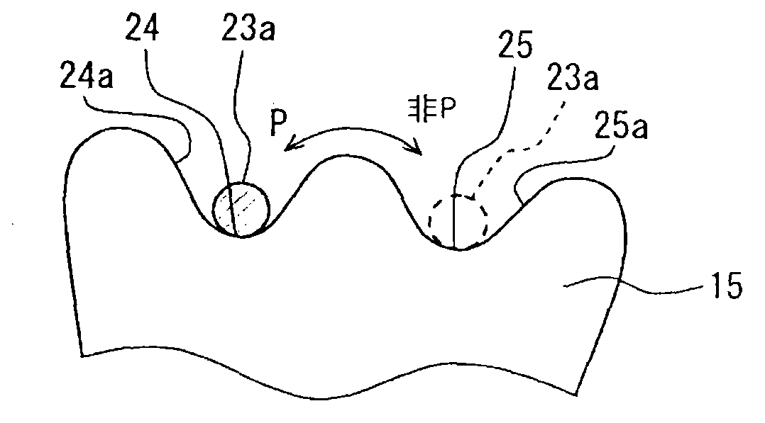
[0026] A parking lever 18 configured in an L shape is fixed to the stopper 15 . A cone 19 provided at a distal end portion of the parking lever 18 is in contact with the lock 21 . The locker 21 rotates upward or downward around the shaft 22 according to the operating position of the cone 19 to lock or unlock the parking gear 20 . The parking gear 20 is supplied to an output shaft of an automatic transmissi...


PUM


Abstract

When a failure of a feedback control operation of an electric motor is sensed, a control unit changes the feedback control operation to an open loop control operation. At the time of executing the open loop control operation, the control unit sequentially changes the exciting phase of the motor without executing feedback of information of the count value of the encoder counter and rotates a rotor of the motor until a count value of an exciting phase change counter reaches an open loop target count value, which corresponds to a target rotational position of the rotor. When the control unit changes the feedback control operation to the open loop control operation, the control unit sets the open loop target count value by correcting a feedback target count value based on an exciting phase deviation correction value for the count value of the encoder counter.

Description

technical field [0001] The present invention relates to motor control devices. Background technique [0002] For example, JP2004-56855A (corresponding to US2004 / 0008002A1) teaches a motor drive system. Here, the content of US2004 / 0008002A1 is fully incorporated herein by reference. In this motor drive system, a feedback control operation (hereinafter referred to as an F / B control operation) is performed as follows. Specifically, the pulse signal of the encoder provided in the motor increases or decreases the count according to the rotation direction of the rotor of the motor. The rotational position of the rotor is sensed based on the count value of the encoder. The rotor is rotated by sequentially changing the excitation phase of the motor until the count value of the encoder reaches the target count value corresponding to the target rotational position of the rotor. In the motor drive system described above, the failure of the F / B control system of the motor is monitor...

Claims


Application Information

Patent Timeline
IPC IPC(8): H02P6/08H02P6/18H02P25/08H02P29/00
CPCG05B2219/42294G05B19/23G05B2219/42095G05B19/4062
Inventor 山田纯
Owner DENSO CORP
Why Eureka
Try Eureka