Aircraft wing and fiber metal laminate forming part of such an aircraft wing

A technology of fiber metal and laminates, applied in the direction of metal layered products, wings, layered products, etc., can solve the problems of reducing the fatigue performance of laminates

Inactive Publication Date: 2013-06-05
CONSTELLIUM ISSOIRE
View PDF6 Cites 4 Cited by
  • Summary
  • Abstract
  • Description
  • Claims
  • Application Information

AI Technical Summary

Problems solved by technology

The aluminum layer exhibits a high shear stiffness, but this solution significantly reduces the fatigue performance of the laminate compared to conventional fiber metal laminates

Method used


Image

  • Aircraft wing and fiber metal laminate forming part of such an aircraft wing
  • Aircraft wing and fiber metal laminate forming part of such an aircraft wing
  • Aircraft wing and fiber metal laminate forming part of such an aircraft wing

Examples


Embodiment Construction

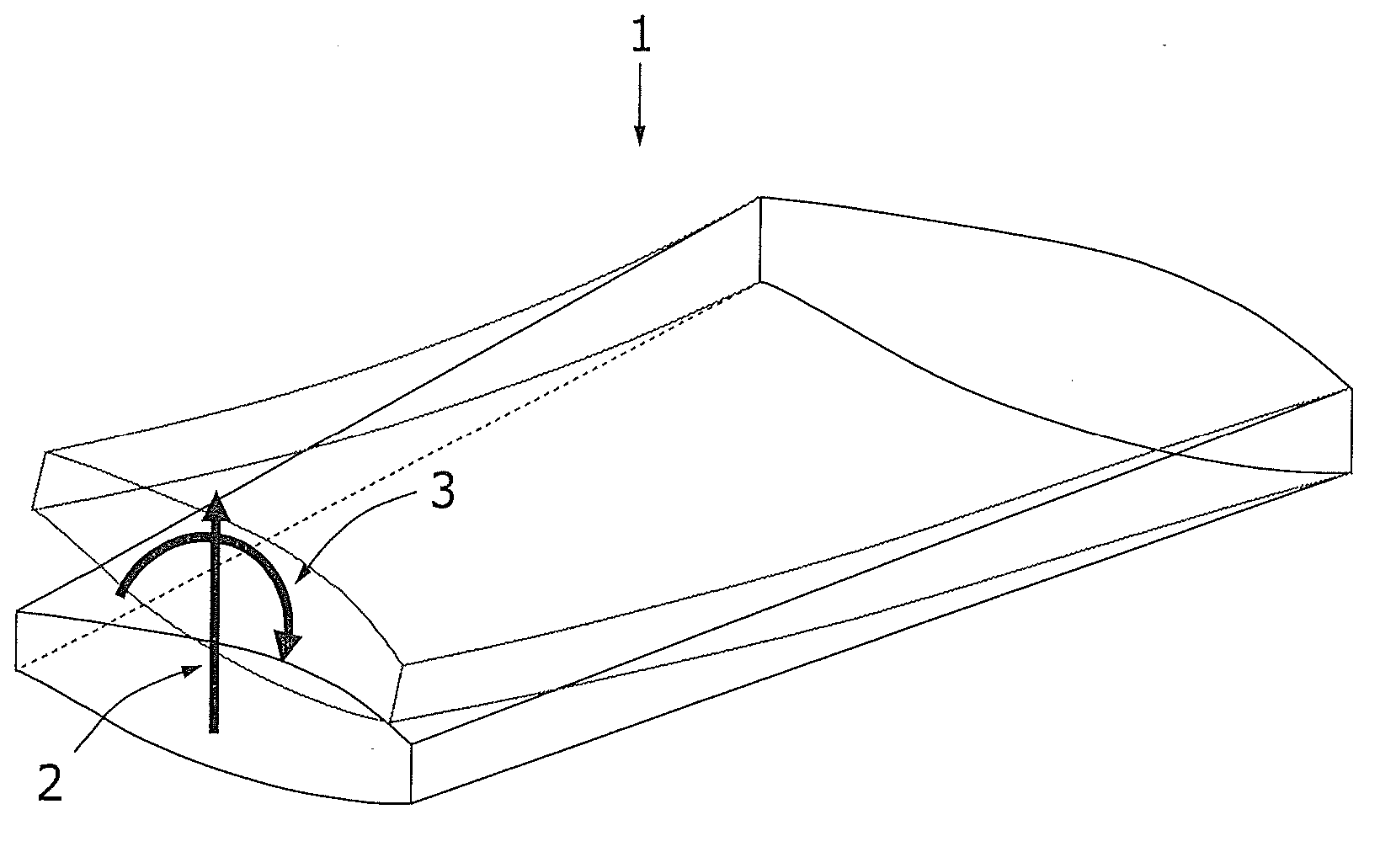
[0029] first reference figure 2 , shows a portion of the wing 1 which, in use, is subjected to an upward bending force indicated by arrow 2 generated by the lift. Wing 1 is also subjected to torsional forces indicated by arrow 3 .

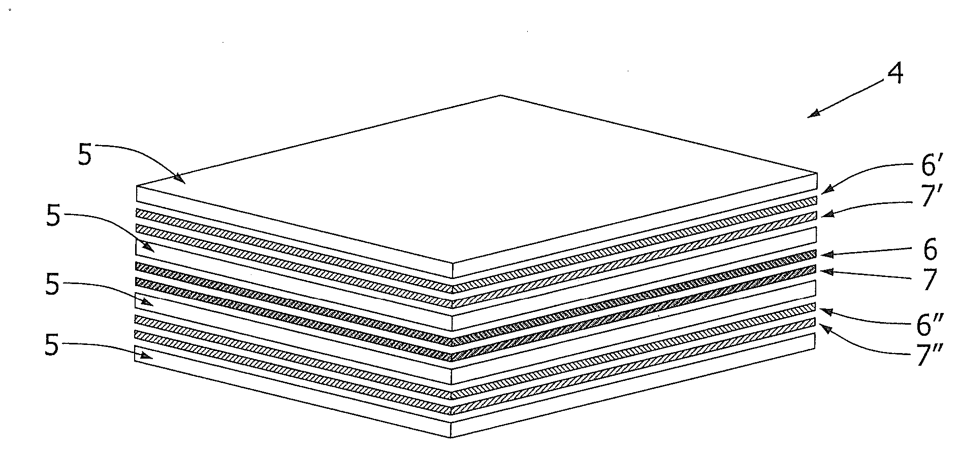
[0030] figure 1 A laminate 4 of the invention is shown comprising a plurality of metal layers 5 and a plurality of layers 6 , 7 of fiber reinforced plastic between said metal layers 5 in or near the plane of symmetry of the laminate 4 . Furthermore, on opposite sides of said fiber reinforced plastic layers 6, 7 in the plane of symmetry of the laminate between the metal layers 5, there are fiber reinforced plastic layers 6', 7' and 6", 7' '. The metal layer 5 and the fiber reinforced plastic layers 6, 7; 6', 7'; 6'', 7'' are all bonded together.

[0031] At least one or some of the fiber reinforced plastic layers 6 ′, 7 ′ and 6 ″, 7 ″ that are not in or near the plane of symmetry of the laminate 4 exhibit a first type of fiber. This longitudi...


PUM

PropertyMeasurementUnit
thicknessaaaaaaaaaa

Abstract

Fiber metal laminate (4)and an aircraft wing (1) having a longitudinal direction, comprising metal layers (5) and fiber reinforced plastic layers (6, 7, 6', 7'; 6'', 7'') in between said metal layers (5),wherein the metal layers (5) and the fiber reinforced plastic layers (6, 7, 6', 7'; 6'', 7'') are bonded together, and wherein the fibers of at least some of the fiber reinforced plastic layers (6, 7, 6', 7'; 6'', 7'') are arranged in a first group in a first plastic layer (6) and in a second group in a second plastic layer (7) whereby the fibers of the first group are at an angle with respect to the fibers of the second group, whereinsaid laminate (4) exhibits fibers of a first type and fibers of a second type, wherein the fibers of the first type being arranged in the said longitudinal direction of the laminate (4) in one or more of its fiber reinforced plastic layers (6', 7'; 6'', 7''), and that it has adjacent fiber reinforced plastic layers (6, 7) at or near a symmetry-plane of the laminate (4) that are provided with the fibers of the second type.

Description

technical field [0001] The present invention relates to a fiber metal laminate comprising a plurality of metal layers and a plurality of fiber reinforced plastic layers between the metal layers, wherein the metal layers and the The layers of fiber reinforced plastic are bonded together, and wherein the fibers of the layer of fiber reinforced plastic are arranged in a first group and a second group whereby the fibers of the first group are relative to the fibers of the second group at an angle. [0002] The invention also relates to an airfoil comprising one or more of said fiber metal laminates. Background technique [0003] A fiber metal laminate as described in the preamble is known from US-A-5,547,735. This known fiber metal laminate includes a bidirectional reinforcement layer comprising about 45-70 volume percent high strength glass fibers. The bi-directional reinforcement layer includes: a central layer comprising glass fibers oriented generally parallel to a first ...

Claims


Application Information

Patent Timeline
Patent Type & Authority Applications(China)
IPC IPC(8): B32B5/12B32B5/26B32B5/28B64C3/20B64C3/26B32B15/08B32B15/14B29C70/20B29C70/22B29C70/08
CPCB32B2250/40B32B2262/101Y02T50/43B32B2260/023B32B2605/18B32B15/14B32B2262/106B32B2262/0269B32B2260/048B64C3/26Y02T50/433B32B15/08B32B5/26B32B5/12B32B5/28B32B2250/42Y10T428/24124Y02T50/40
Inventor R·C·阿尔德里埃斯滕R·贝内迪克特斯
Owner CONSTELLIUM ISSOIRE
Why Eureka
Try Eureka