Fiber metal laminate, preparation method and electronic equipment
A fiber metal, electronic device technology, applied in the field of materials
- Summary
- Abstract
- Description
- Claims
- Application Information
AI Technical Summary
Problems solved by technology
Method used
Image

Examples
preparation example Construction
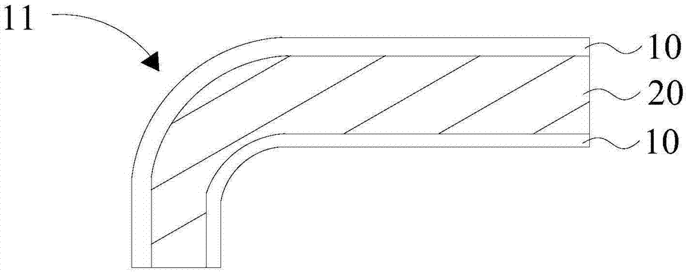
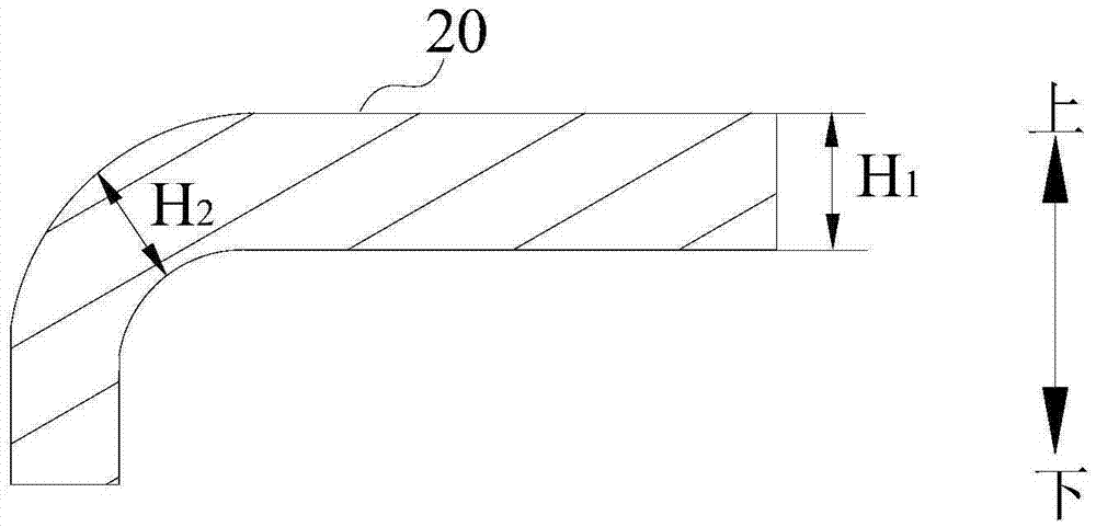
[0027] Based on the current preparation technology, in the flat part of the fiber metal laminate, the thickness control of the fiber layer 20 is relatively easy to meet the product requirements, the actual product thickness is not much different from the predetermined product thickness, and the production yield is high. However, because the preparation of fiber-metal laminates often requires hot-press molding, and the resin contained in the fiber layer 20 is in a molten state when heated, it can flow in the space between the metal plates 10, and it is very easy to overflow under pressure, and then The thickness of the fiber layer 20 causing the bent portion is not uniform. Moreover, due to the overflow of the resin, gaps are formed between the metal plates 10, which makes it difficult to bend the metal plate 10, and it is also difficult for the prepared bent portion 11 to meet the design of the fiber metal laminate for the bent portion 11. Usually, the bent portion 11 of the pr...
Embodiment 1
[0064] Cut the fiber prepreg into a shape of 100×200mm, stack four layers, and set aside.
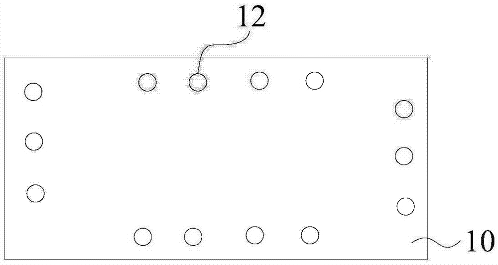
[0065] The length and width of the two metal plates are both 100×200mm, and the thickness is 0.2mm, which are metal 1 and metal 2 respectively. The surrounding area of metal 2 is drilled with laser, the aperture is 0.05mm, the laser machine adopts Han’s YLP-20 machine, the laser current is 15A, the speed is 500mm / s; the area of the hole is 50mm×10mm. Two microholes are set on the long side, and one microhole is set on the short side for spare.
[0066] Cut the double-sided foam tape into a shape corresponding to the shape of the metal plate (such as Figure 5 in the shape of part 30), spare.
[0067] Lay the fiber material on top of the metal 2, and then spread foam double-sided adhesive around the metal 2, and bond the metal 1 together to form a closed cavity.
[0068] Put the above-mentioned bonded metal fiber composite material into a mold (the mold has a curved part) for hot ...
Embodiment 2
[0070] Cut the fiber prepreg into a shape of 100×200mm, stack four layers, and set aside.
[0071] The length and width of the two pieces of metal are both 100×200mm, and the thickness is 0.2mm, which are metal 1 and metal 2 respectively. The surrounding area of metal 2 is drilled with laser, the aperture is 0.05mm, the laser machine adopts Han’s YLP-20 machine, the laser current is 15A, and the speed is 500mm / s; the area of the long side hole is 50mm×10mm, and two places can be set; The area of the hole on the side is 50mm×10mm, and it is reserved.
[0072] Spread the fiber material on top of the metal 2, and then dispense glue around the metal 2 to bond the metal 1 together to form a closed cavity.
[0073] Put the above-mentioned bonded metal fiber composite material into a mold (the mold has a curved part) for hot-press molding at a temperature of 150 degrees, a pressure of 30kg, and a time of 30 minutes to obtain a product blank, and then use a CNC machine tool to ...
PUM
| Property | Measurement | Unit |
|---|---|---|
| pore size | aaaaa | aaaaa |
| pore size | aaaaa | aaaaa |
| pore size | aaaaa | aaaaa |
Abstract
Description
Claims
Application Information
 - R&D
- Intellectual Property
- Life Sciences
- Materials
- Tech Scout
- Unparalleled Data Quality
- Higher Quality Content
- 60% Fewer Hallucinations
Browse by: Latest US Patents, China's latest patents, Technical Efficacy Thesaurus, Application Domain, Technology Topic, Popular Technical Reports.
© 2025 PatSnap. All rights reserved.Legal|Privacy policy|Modern Slavery Act Transparency Statement|Sitemap|About US| Contact US: help@patsnap.com