Fiber metal laminated plate and preparation method thereof
A technology of fiber metal and laminated boards, applied in the direction of metal layered products, chemical instruments and methods, lamination, etc., can solve the problems of weak bonding force and achieve the effect of strong bonding force
- Summary
- Abstract
- Description
- Claims
- Application Information
AI Technical Summary
Problems solved by technology
Method used
Image

Examples
preparation example Construction
[0037] The present invention also provides a method for preparing a fiber-metal laminate, wherein the method includes: coating the surface of the metal layer with an adhesive formed of a resin composition containing a thermosetting adhesive resin and magnetic chopped fibers , and under the action of a magnetic field, the magnetic chopped fibers in the binder are erected so that the angle between the magnetic chopped fibers and the metal layer is greater than 0°, and the prepreg fiber cloth and the metal layer The layers are stacked so that the surface with the adhesive on the metal layer faces the prepreg fiber cloth, and then hot pressing is performed to combine the prepreg fiber cloth and the metal layer into one body to obtain the fiber metal laminate.
[0038] In addition, in order to obtain a fiber-metal laminate with excellent bonding force between the metal layer and the fiber layer, the angle between the erected magnetic chopped fibers and the metal layer is preferably ...
Embodiment 1
[0072] 1. Preparation of binder
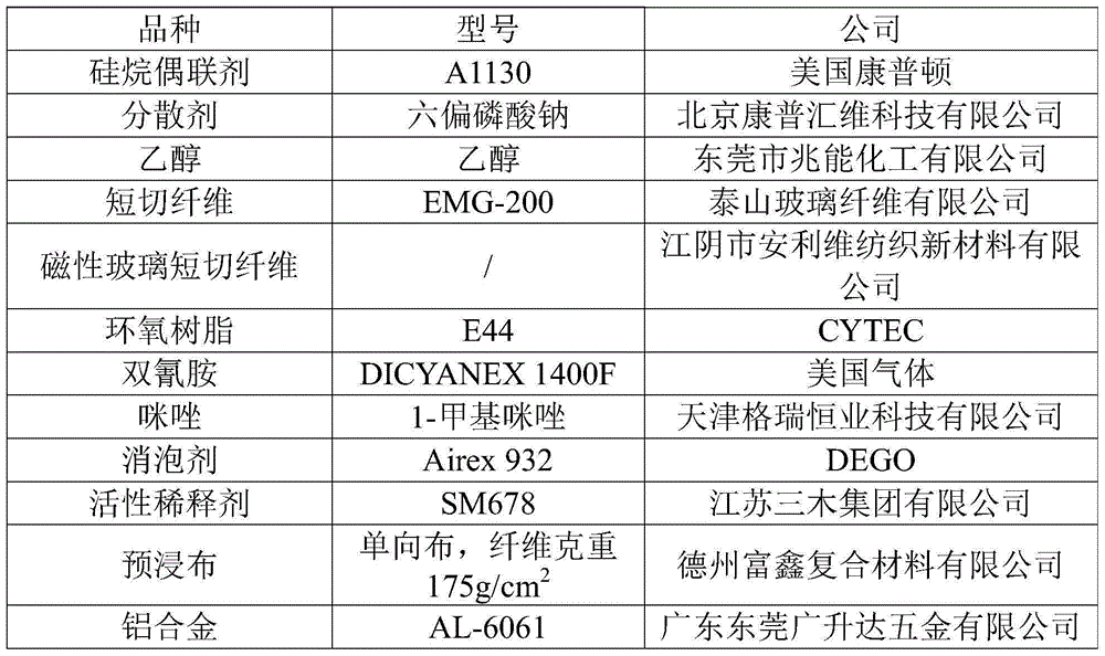
[0073] 1) Prepare the pretreatment agent according to the ratio (mass ratio) of silane coupling agent: dispersant: ethanol = 1:3:100;
[0074] 2) Spray the pretreatment agent on the surface of 4kg (magnetic glass chopped fibers, the length is 200 μm, and the cross-sectional diameter is 10um), and dry to obtain the pretreatment fiber filament X;
[0075] 3) Weigh 48kg of epoxy resin and 25kg of reactive diluent, and disperse with a high-speed disperser (purchased from Shanghai Farfly Energy Co., Ltd., the same below) to obtain mixture A;
[0076] 4) Add the pretreated fiber filament X obtained in step 2) into mixture A, and disperse with a high-speed disperser to obtain mixture B;
[0077] 5) Weigh 15kg of dicyandiamide (curing agent), 5kg of 1-methylimidazole (curing accelerator), and 3kg of defoamer, add them to mixture B, and disperse with a high-speed disperser to obtain a binder;
[0078] 6) Cut the aluminum alloy into a size (2 pieces) ...
Embodiment 2
[0082] 1) Prepare the pretreatment agent according to the ratio (mass ratio) of silane coupling agent: dispersant: ethanol = 1:3:100;
[0083] 2) Spray a pretreatment agent on the surface of 8 kg of magnetic chopped fibers (magnetic glass chopped fibers, the length is 200 μm, and the cross-sectional diameter is 10 μm), and dry to obtain the pretreated fiber filament X;
[0084] 3) Take 75kg of epoxy resin and 10kg of reactive diluent, and disperse with a high-speed disperser to obtain mixture A;
[0085] 4) Add the pretreated fiber filament X obtained in step 2) into mixture A, and disperse with a high-speed disperser to obtain mixture B;
[0086] 5) Weigh 5 kg of dicyandiamide (curing agent), 0.7 kg of 1-methylimidazole (curing accelerator), and 1.3 kg of defoamer, add them to mixture B, and disperse with a high-speed disperser to obtain a binder;
[0087] 6) Cut the aluminum alloy into a size (2 pieces) with a length and width of 200 mm×100 mm, put it into 5 wt % nitric aci...
PUM
| Property | Measurement | Unit |
|---|---|---|
| Angle | aaaaa | aaaaa |
| Length | aaaaa | aaaaa |
| Length | aaaaa | aaaaa |
Abstract
Description
Claims
Application Information
 - R&D
- Intellectual Property
- Life Sciences
- Materials
- Tech Scout
- Unparalleled Data Quality
- Higher Quality Content
- 60% Fewer Hallucinations
Browse by: Latest US Patents, China's latest patents, Technical Efficacy Thesaurus, Application Domain, Technology Topic, Popular Technical Reports.
© 2025 PatSnap. All rights reserved.Legal|Privacy policy|Modern Slavery Act Transparency Statement|Sitemap|About US| Contact US: help@patsnap.com