Sewing machine

A sewing machine and upper thread technology, which is applied in the field of sewing machines, can solve problems such as broken upper thread J, unsmooth upper thread J, unstable resistance value, etc., and achieve the effect of reducing the possibility of thread breakage

Active Publication Date: 2013-06-05
NSD
View PDF6 Cites 4 Cited by
  • Summary
  • Abstract
  • Description
  • Claims
  • Application Information

AI Technical Summary

Problems solved by technology

[0008] But when Figure 47 In the existing structure shown, since the frictional resistance produced by the clamping plate 95 and the frictional resistance produced by the rotating tensioner 94 are always applied on the surface line J, this frictional resistance is unstable as a resistance value (not necessarily ), so it is difficult to control the tension applied to the upper thread according to the stitches
Moreover, in the case of having a plurality of needle bars on one head or in the case of a multi-head embroidery sewing machine, it is difficult to make the resistance value of the upper thread of the tension plate and the rotary tensioner the same for each upper thread on one head. It is difficult to equalize the tension applied to each upper thread
[0009] Moreover, in Figure 47 In this structure, although the upper thread J is pulled out from the winding thread 98 when the thread take-up lever 12a is pulled up, the frictional resistance generated by the tension plate 95 and the friction generated by the turning tension force 94 are applied to the upper thread J at this time. resistance, and since this frictional resistance is unstable, the upper thread J cannot be pulled out smoothly from the winding thread 98.
Moreover, since the upper thread J is pulled out when the thread take-up lever 12a is pulled up, the upper thread J is pulled out in a short time, and the frictional resistance generated by the tension plate 95 and the frictional resistance generated by the rotary tensioner 94 are applied to the upper thread J, So there is a possibility that the upper thread J is disconnected due to these frictions
[0010] Also, in the event that the upper thread J is disconnected, the Figure 47 In the structure of , although the thread breakage can be detected because the rotary tensioner 94 does not rotate, since slippage occurs between the rotary tensioner 94 and the upper thread J, there are cases where the thread breakage does not occur and the rotary tensioner 94 does not rotate. , the broken thread of the upper thread cannot be detected correctly.
[0011] Furthermore, in the thread supply device for the sewing machine described in Patent Document 1, the tension of the thread cannot be controlled because the thread reeling member only moves to a position where the thread is not reeled when the seam is formed.
Moreover, in a common sewing machine, since the period of the thread take-up lever rising does not correspond to the time of seam formation, but corresponds to the time of cloth feeding, in the thread supply device of Patent Document 1, since the thread take-up lever rises, the The downstream side gripper is closed, so it is not possible to control the tension of the line
Moreover, in the thread supply device of Patent Document 1, since the thread reeling member pulls out a certain amount of thread, there are too many or too few threads stored in the thread during cloth feeding due to the difference in thread consumption of each stitch.

Method used


Image

  • Sewing machine
  • Sewing machine
  • Sewing machine

Examples


Embodiment 1

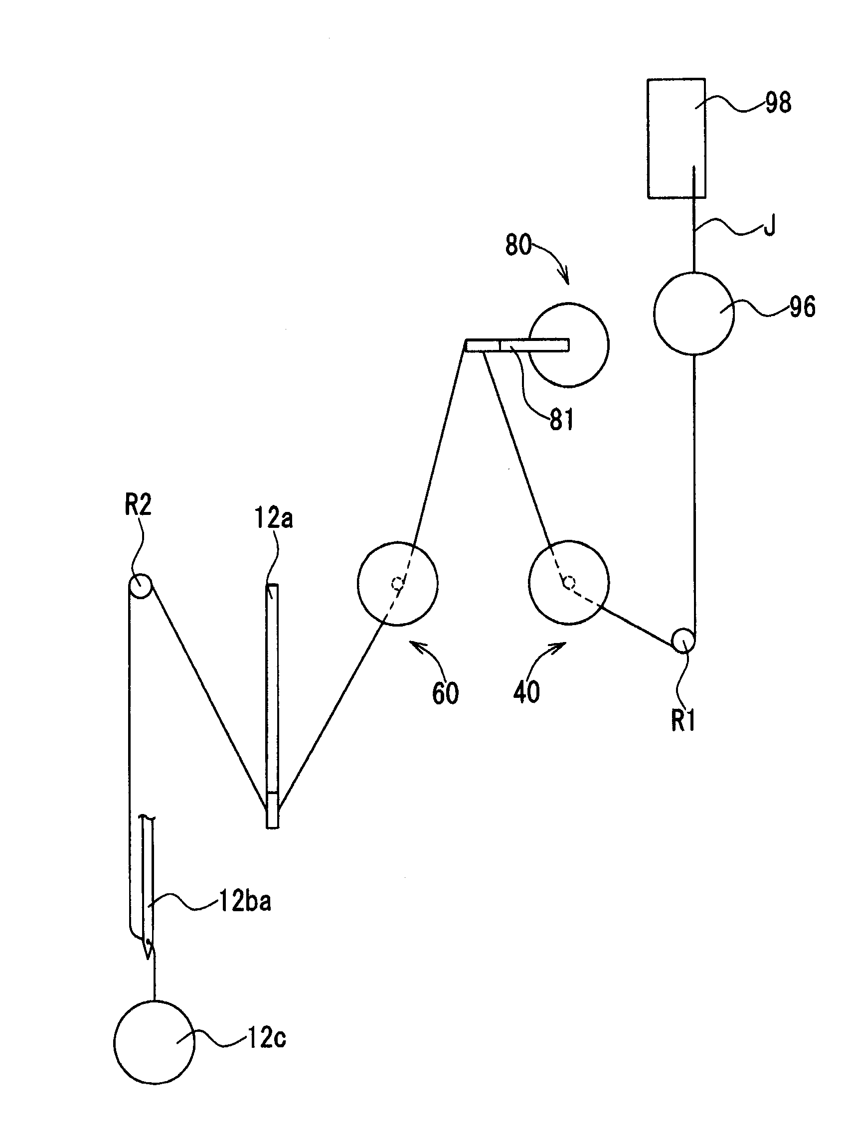
[0188] Based on the sewing machine 5 of Embodiment 1 of the present invention such as Figure 1 to Figure 5 As shown in the structure, it has: head 7, shuttle 12c, sewing frame (or holding frame, embroidery frame) 12d, frame driving device 24, and storage device 92. in addition, figure 2 is a drawing conceptually showing the main parts of the sewing machine 5, image 3 specifically expressed figure 2 Content.

[0189] Here, the machine head 7 is provided above a substantially flat sewing machine table (not shown). That is to say, frame 120 is erected from the upper surface of the sewing machine table (refer to image 3 , Figure 4 ), the machine head 7 is provided on the front side (Y1 side) of the frame 120 .

[0190] Head 7 such as figure 1 , image 3 , Figure 4 As shown in the structure, it has: mechanical element group 10, spindle motor 20, spindle 22, upper thread control part 30, control circuit 90, pretensioner 96, winding thread 98 wound on the upper threa...

Embodiment 2

[0295] Next, the sewing machine of the second embodiment will be described. The sewing machine 205 based on Embodiment 2 is an embroidery sewing machine, such as Figure 25 ~ Figure 28 As shown in the structure, it has: a head (embroidery head) 207, a shuttle 12c, a sewing frame 12d, a frame driving device 24, and a storage device 92. The sewing machine 205 is a multi-needle sewing machine, specifically, a six-needle embroidery sewing machine capable of handling six types of upper threads.

[0296] Here, the machine head 207 is provided above a substantially flat sewing machine table (not shown) similarly to the machine head 7 . That is, a frame 320 is erected from the upper surface of the sewing machine table (refer to Figure 27 ), a machine head 207 is provided on the front side of the frame 320 .

[0297] Head 207 as Figure 25 ~ Figure 28 The structure shown in the figure includes: a mechanical element group 10 , a spindle motor 20 , a spindle 22 , a needle thread con...

Embodiment 3

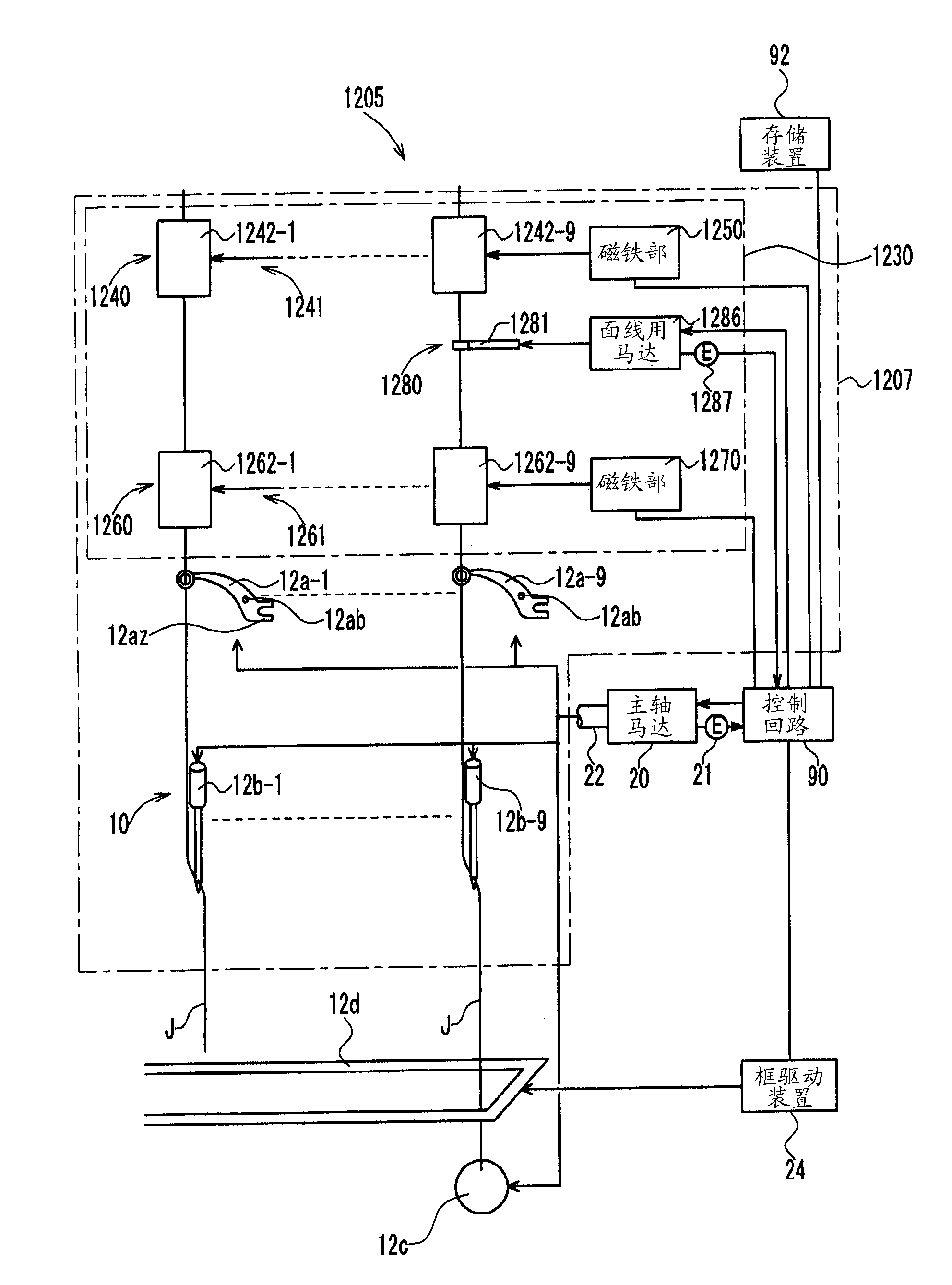
[0366] Next, the sewing machine of the third embodiment will be described. The sewing machine 1205 based on Embodiment 3 is an embroidery sewing machine, such as Figure 29 ~ Figure 36 As shown in the structure, it has: head (embroidery head) 1207, shuttle 12c, sewing frame 12d, spindle motor 20, spindle 22, frame drive device 24, control circuit 90, and storage device 92. This sewing machine 1205 is a multi-needle sewing machine, specifically, a 9-needle embroidery sewing machine that can handle nine types of upper threads.

[0367] in addition, Figure 33 , Figure 34 Only the needle thread control mounting part 1340 and the needle thread control part 1230 are placed on the Figure 32 The left side view of the partial cross-section cut at the P-P position in the middle, Figure 35 Only the needle thread control mounting part 1340 and the needle thread control part 1230 are placed on the Figure 32 Partial cross-sectional left side view cut at Q-Q position in middle. an...


PUM


Abstract

Disclosed is needle yarn tension control device that can control the amount of tension in a needle yarn for each stitch, can draw out the needle yarn, provides little risk of yarn breakages, readily and accurately detects any yarn breakages, and has no excess or insufficient amount of accumulated yarn from pulling out the needle yarn. Said needle yarn tension control device comprises an upstream grip (40) that grips the needle yarn, a downstream grip (60), and a rotating section (80) that rotates the needle yarn. In a torque control section, a balance (12a) applies rotational force to a rotating arm in accordance with a torque value such that tension is applied to the needle yarn against the direction that the needle yarn is pulled, while an upstream grip main body (41) is closed and a downstream grip main body (61) is open. In the position control section, the balance applies rotational force to the rotating arm (81) in accordance with position data for the angle of a needle yarn motor (86) such that the needle yarn motor angle returns to an initial position for the needle yarn motor (86) angle, while the upstream side grip main body (41) is open and the downstream side grip main body (61) is closed.

Description

technical field [0001] The present invention relates to a sewing machine (especially an embroidery sewing machine), and in particular to the control of the upper thread tension in the sewing machine. Background technique [0002] In existing sewing machines, such as Figure 47 As shown, the upper thread J passes through the pretensioner (pretension) 96, the tension plate 95, the rotary tensioner (rotary tension) 94, the tension spring (commonly known as the suspension spring) from the winding thread 98 wound on the upper thread bobbin. 93 to the thread take-up lever 12a, and then to the needle 12ba. [0003] Moreover, existing sewing machines such as Figure 48 composition shown. The needle bar case 2314 that slides in the left-right direction relative to the arm 2312 has a needle bar case main body 2330 provided with the thread take-up lever 12a, the needle bar 12b, the thread tension spring 93, etc., and is fixedly arranged on the upper surface of the needle bar case mai...

Claims


Application Information

Patent Timeline
Patent Type & Authority Applications(China)
IPC IPC(8): D05B47/04D05B45/00
CPCD05B47/04D05B51/00D05C11/08D05B45/00
Inventor 泷泽义知仓岛达洋小野政义
Owner NSD
Why Eureka
Try Eureka