
Method for manufacturing site pipeline type expansion joint

A manufacturing method and technology for expansion joints, which are applied to expansion compensation devices, pipe components, pipes/pipe joints/pipe fittings for pipelines, etc. Environmental impact, ensuring safe production, and reducing the effect of downtime

Inactive Publication Date: 2013-06-12
CHINA 19TH METALLURGICAL CORP
View PDF8 Cites 2 Cited by
  • Summary
  • Abstract
  • Description
  • Claims
  • Application Information

AI Technical Summary

Problems solved by technology

[0003] 1. Short service life: The original expansion joint is made of stainless steel corrugated expansion joints, and its expansion coefficient can meet its use in high temperature environments, but the stainless steel of the corrugated joints is too thin, resulting in a short service life
[0004] 2. High cost of the enterprise: due to its thin corrugation, if the thickness of the corrugated stainless steel is increased during production, the manufacturing process and cost will increase, making the already high cost even more unbearable for the enterprise
[0005] 3. Difficulty in inspection and maintenance: the expansion of the expansion joint is realized by the expansion and contraction of the corrugation, but once it is corroded and perforated, it is basically irreparable, and its replacement is very time-consuming. Once it is replaced, it will cause the upper level of copper Smelting enterprises and sulfuric acid production enterprises stopped production at the same time, which brought immeasurable losses to the enterprises

Method used


Image

  • Method for manufacturing site pipeline type expansion joint
  • Method for manufacturing site pipeline type expansion joint
  • Method for manufacturing site pipeline type expansion joint

Examples


Embodiment Construction

[0028] The present invention will be further described below in combination with embodiments.

[0029] Such as figure 1 , 2 , 3, 4, 5, 6, 7, and 8, the manufacturing method of the on-site pipeline expansion joint includes the following steps:

[0030] A. Select ribbed plate and coiled tube plate;

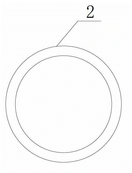
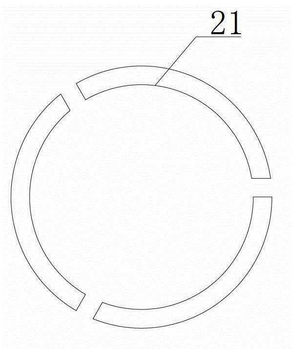
[0031] B. Cut the ribbed plate into a ring-shaped ribbed plate 2, so that the inner diameter of the ribbed plate 2 is equal to the outer diameter of the pipeline 1;

[0032] C. Make the inner diameter part of the rib plate 2 close to the outer circumference of the pipeline 1, and let the inner diameter part of the rib plate 2 be sealed and welded with the outer circumference of the pipeline 1, so that the rib plate 2 protrudes outside the pipeline 1;

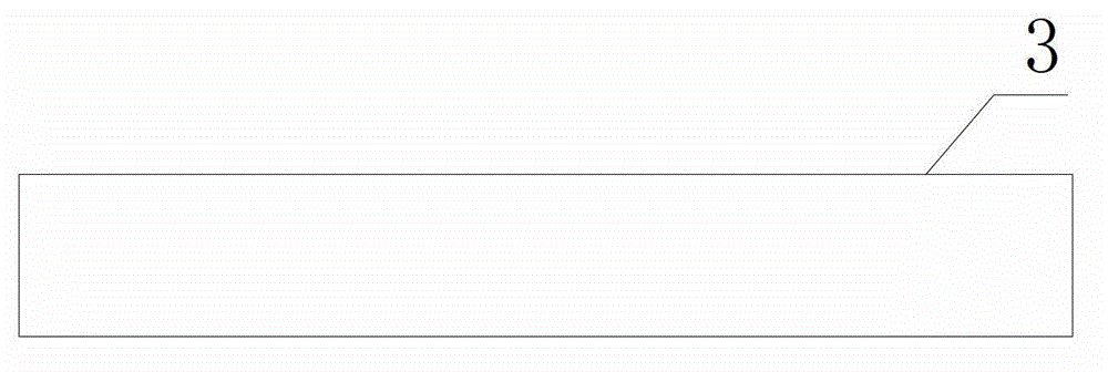
[0033] D, the coiled tube sheet is cut into a coiled tube 3 whose width is equal to the distance between two adjacent ribs 2;

[0034] E. Seal and weld the long side of the coiled tube 3 and the outer circumference of the two adja...


PUM


Abstract

The invention discloses a method for manufacturing a site pipeline type expansion joint in the environment with larger environmental temperature change and strong corrosivity, which has the characteristic of convenience in overhauling and maintenance. The method comprises the following steps: step A, selecting a reinforcement plate material and a roll bending material; step B, cutting the reinforcement plate material into a circular-ring-shaped reinforcement plate, wherein the inner diameter of the reinforcement plate is equal to the outside diameter of a pipeline; step C, enabling an inner diameter part of the reinforcement plate to be clung to the outer circumference of the pipeline so as to enable the inner diameter part of the reinforcement plate to be sealed and welded with the outer circumference of the pipeline to cause the reinforcement plate to protrude outside the pipeline; step D, cutting the roll bending material into a roll bending plate of which the width is equal to the distance between two adjacent reinforcement plates; and step E, performing sealing and welding on a long side part of the roll bending plate and an outer circumference part of the two adjacent reinforcement plates to enable the roll bending plate and the two reinforcement plates to form a pipeline type expansion joint waviness with a cavity. According to the method, the material of the expansion joint can be selected according to the environment; multiple times of repair, local replacement and repeated use can be realized; and the site pipeline type expansion joint can replace a finished stainless steel waviness expansion joint.

Description

technical field [0001] The invention relates to a manufacturing method of an on-site pipeline expansion joint used in environments with large ambient temperature changes and strong corrosiveness. Background technique [0002] The flue gas produced by copper smelters contains very heavy sulfur and cannot be discharged outside. Therefore, pipes are used to collect flue gas to make sulfuric acid. In practical applications, pipes transport SO 2 During the actual use of the high-temperature flue gas, the expansion joint will be corroded and perforated by the condensed acid produced by the condensation of the flue gas in about 3 to 5 months under normal circumstances. The previous method used to make a jacket and fill it with cement for sealing , leak-proof, but in the process of stopping and resuming production, the expansion of the pipeline cannot be achieved by thermal expansion and contraction, so the pipeline will crack every time the production is stopped and resumed, and th...

Claims


Application Information

Patent Timeline
Patent Type & Authority Applications(China)
IPC IPC(8): B23P15/00F16L51/00
Inventor 陈洪泽杨洪涂林立罗崇勇
Owner CHINA 19TH METALLURGICAL CORP
Learn More