Pipe coiling device of cooling fin cleaning machine

A technology for cooling fins and cleaning machines, applied in the fields of cleaning machines and coiling devices, can solve the problems of coiling of composite tubes that are not suitable for cooling fin cleaning machines, unreasonable scheme design, and low degree of automation, etc. Ideal effect, simple structure and high degree of automation

Inactive Publication Date: 2013-06-12
江苏科能电力机械有限公司
View PDF1 Cites 3 Cited by
  • Summary
  • Abstract
  • Description
  • Claims
  • Application Information

AI Technical Summary

Problems solved by technology

[0004] Although the above scheme can be used for coiling the tube, the design of the program is not reasonable enough and the degree of automation is low. It is not suitable for coiling the composite tube of the cooling fin cleaning machine, and it is impossible to provide air and water to the tube body while coiling the tube body. , and technical problems such as irregular winding

Method used


Image

  • Pipe coiling device of cooling fin cleaning machine
  • Pipe coiling device of cooling fin cleaning machine
  • Pipe coiling device of cooling fin cleaning machine

Examples


Embodiment Construction

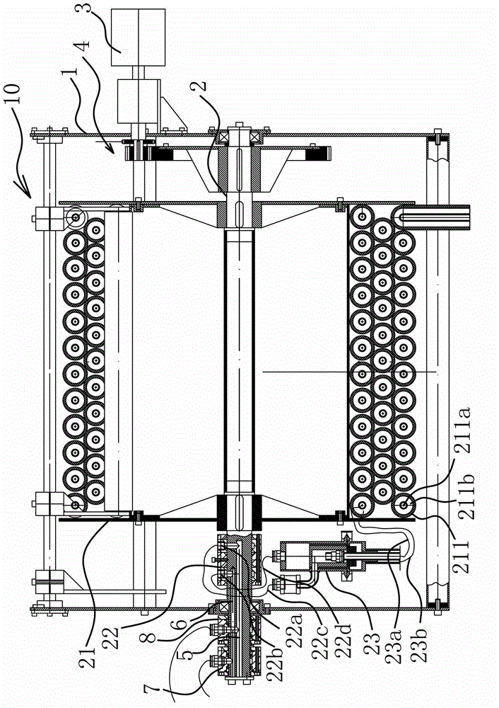
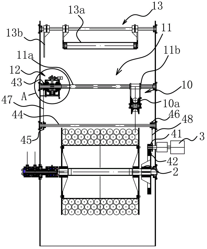
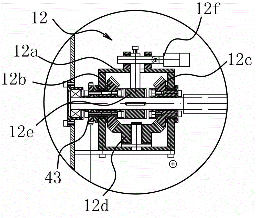
[0035] Such as Figure 1-7 As shown, the coiling device of the cooling fin cleaning machine includes a frame 1 and a rotating shaft 2 arranged on the frame 1, on which a coiling cylinder 21 is fixed, and the frame 1 is provided with a driver 3, and the driver 3. Connected to the rotating shaft 2 through the transmission mechanism 4 and can drive the rotating shaft 2 to rotate. One end of the rotating shaft 2 is provided with a liquid inlet channel 5 and an air inlet channel 6. Mechanism 8, the intake end of the intake channel 6 is provided with a rotary intake mechanism 7 that is rotatably connected to the rotating shaft 2, and the rotating shaft 2 is fixed with an output sleeve located at the liquid outlet end of the liquid inlet channel 5 and the gas outlet end of the intake channel 6 22. The output sleeve 22 is provided with a liquid outlet hole 22a connected with the liquid inlet passage 5 and an air outlet hole 22b connected with the air inlet passage 6. The composite de...


PUM


Abstract

The invention belongs to the technical field of cleaning devices, relates to a cleaning machine, in particular to a pipe coiling device of a cooling fin cleaning machine, and solves the technical problems of non-reasonability and the like in the prior art. A liquid inlet channel and an air inlet channel are formed in one end of a rotary shaft; a rotary liquid inlet mechanism rotationally connected with the rotary shaft is arranged at the liquid inlet end of the liquid inlet channel; a rotary air inlet mechanism rotationally connected with the rotary shaft is arranged at the air inlet end of the air inlet channel; an output sleeve positioned at the liquid outlet end of the liquid inlet channel and the air outlet end of the air inlet channel is fixed to the rotary shaft; a liquid outlet hole communicated with the liquid inlet channel and an air outlet hole communicated with the air inlet channel are formed in the output sleeve; and the liquid outlet hole and the air outlet hole are communicated with composite conveying pipes wound on coiling barrels respectively. Compared with the prior art, the pipe coiling device has the advantages of being reasonable in design, simple in structure, convenient to use and operate, ideal in pipe coiling effect, high in automation level and capable of meeting the cleaning requirements of different cooling fin cleaning machines.

Description

technical field [0001] The invention belongs to the technical field of cleaning devices, and relates to cleaning machines, in particular to a coiling device for cooling fin cleaning machines. Background technique [0002] The air cooler is a device that uses ambient air as the cooling medium and sweeps the outside of the finned tube to cool or condense the high-temperature process fluid in the tube. It is referred to as "air cooler" or "air-cooled heat exchanger". The air cooler is an independent set of equipment, which can be placed indoors or outdoors according to user requirements, and can be connected to the equipment with hoses or steel pipes. In order to increase the heat exchange rate, fans are usually used to enhance the fluidity of the air. Due to their strong cooling and heat dissipation capabilities and water saving, they are widely used in petroleum, chemical, energy, metallurgy, aerospace and other fields. Among them, after a period of use, the fins of the air ...

Claims


Application Information

Patent Timeline
IPC IPC(8): B65H75/38B65H75/44
Inventor 王科远
Owner 江苏科能电力机械有限公司
Why Eureka
Try Eureka