Vertically-horizontally arranged hollow heat-proof and sound-proof self-thermal-insulation brick
A technology of heat insulation, sound insulation and self-heat insulation, applied in building components, buildings, building structures, etc., can solve problems such as difficulty in meeting pressure bearing capacity
- Summary
- Abstract
- Description
- Claims
- Application Information
AI Technical Summary
Problems solved by technology
Method used
Image

Examples
Embodiment 1
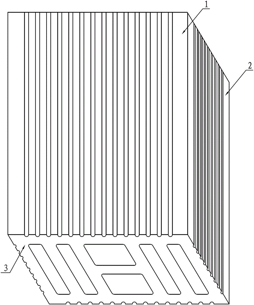
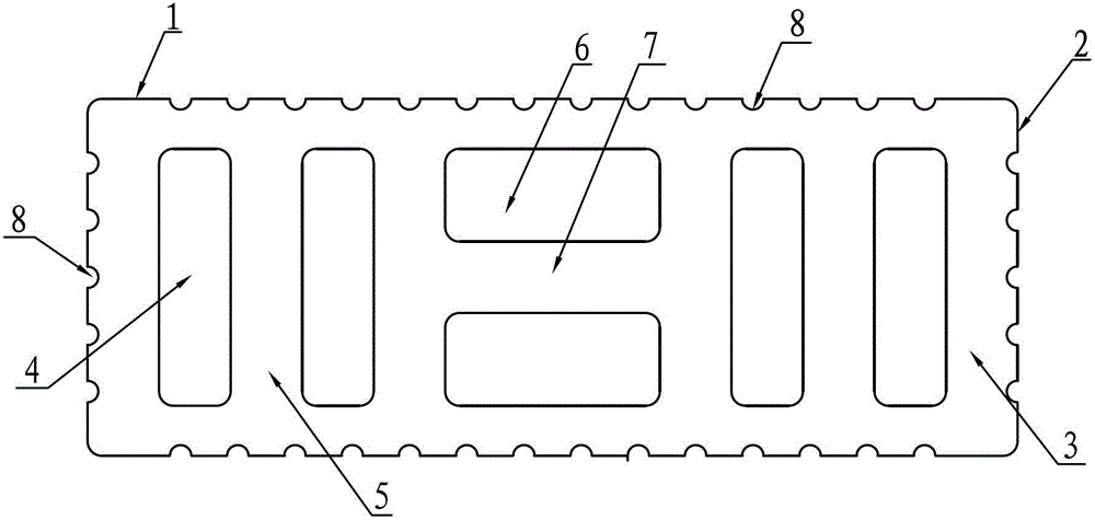
[0023] Embodiment 1: A heat-insulation and sound-insulation self-insulation hollow brick arranged vertically and horizontally, such as Figure 1~3 As shown, it is a six-hole brick, including an upper and lower pressure-bearing surface 1, an outer surface 2 and a butt joint surface 3. On the butt joint surface 3, there are four vertical thermal insulation and sound insulation cavities 4, two horizontal thermal insulation and sound insulation cavities 6, and the The horizontal heat preservation and sound insulation chamber 6 is located in the middle of the brick body butt joint surface 3, and two vertical heat preservation and sound insulation chambers 4 are respectively arranged on both sides of the horizontal heat preservation and sound insulation chamber 6, and a vertical heat preservation and sound insulation chamber 4 is formed between the two vertical heat preservation and sound insulation chambers 4 The pressure ribs 5 form a horizontal pressure rib 7 between two horizonta...
Embodiment 2
[0024] Embodiment 2: as Figure 4 As shown, it is a seven-hole brick. The difference from Example 1 is that three vertical heat insulation and sound insulation cavities 4 and four horizontal heat insulation and sound insulation cavities 6 are arranged at intervals on the butt joint surface 3 of the brick body. There are two horizontal heat insulation and sound insulation chambers 6 distributed up and down between each of the vertical heat insulation and sound insulation chambers 4. The distance from the outer surface 2 to the adjacent vertical heat insulation and sound insulation chamber 4 is 15 to 25 mm, and the upper and lower pressure surfaces 1 to the vertical The distance between the straight thermal insulation and sound insulation cavity 4 is 10 to 15 millimeters, and the distance from the upper and lower pressure bearing surfaces 1 to the adjacent horizontal thermal insulation and sound insulation cavity 6 is 10 to 15 millimeters.
Embodiment 3
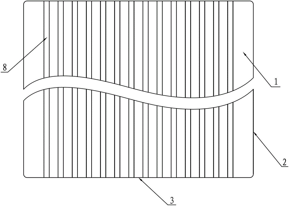
[0025] Embodiment 3: Compared with Embodiment 1, the difference is that there is an angle between the long side of the slurry tank 8 and the brick body, and in this example, the angle between the long side of the slurry tank 8 and the brick body is 15°~45°.
PUM
| Property | Measurement | Unit |
|---|---|---|
| Depth | aaaaa | aaaaa |
| Height | aaaaa | aaaaa |
Abstract
Description
Claims
Application Information
 - R&D
- Intellectual Property
- Life Sciences
- Materials
- Tech Scout
- Unparalleled Data Quality
- Higher Quality Content
- 60% Fewer Hallucinations
Browse by: Latest US Patents, China's latest patents, Technical Efficacy Thesaurus, Application Domain, Technology Topic, Popular Technical Reports.
© 2025 PatSnap. All rights reserved.Legal|Privacy policy|Modern Slavery Act Transparency Statement|Sitemap|About US| Contact US: help@patsnap.com