
High efficiency bistable electromagnetic clutch

An electromagnetic clutch and bistable technology, applied in the field of drive, can solve problems such as excessive size, difficult control, mechanical impact, etc.

Active Publication Date: 2013-06-12
HARBIN INST OF TECH
View PDF4 Cites 2 Cited by
  • Summary
  • Abstract
  • Description
  • Claims
  • Application Information

AI Technical Summary

Problems solved by technology

[0003] The purpose of the present invention is to provide a high-efficiency bistable electromagnetic clutch. In order to solve the existing clutch structure and the energization method, it is necessary to apply a large current to generate sufficient starting force. , the force generated in the middle is too large, dozens of times the starting force, it is difficult to control, and even mechanical impact and noise will be generated, which cannot really meet the requirements of reducing consumption and noise of white goods

Method used


Image

  • High efficiency bistable electromagnetic clutch

Examples


specific Embodiment approach 1

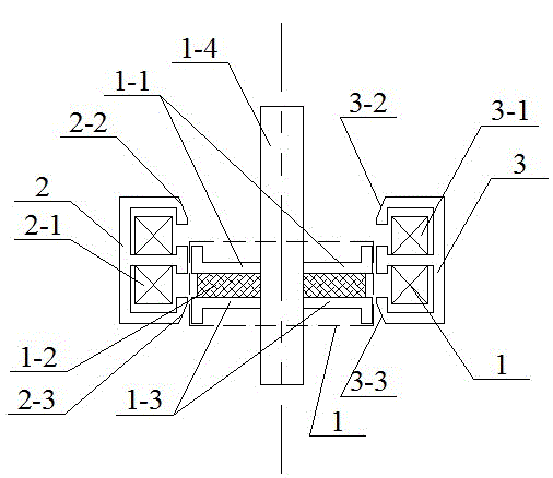
[0008] Specific implementation mode one: as figure 1 As shown, it is composed of a mover 1, a first stator 2, and a second stator 3;

[0009] The mover 1 is composed of an upper disc-shaped magnetizer 1-1, a disc-shaped permanent magnet 1-2, a lower disc-shaped magnetizer 1-3, and a central axis 1-4; the upper disc-shaped magnetizer 1- The lower end face of 1 connects the upper end face of disc-shaped permanent magnet 1-2, and the lower end face of disc-shaped permanent magnet 1-2 connects the upper end face of lower disc-shaped magnetizer 1-3; Last disc-shaped magnetizer 1- The center hole of 1, the center hole of the disc-shaped permanent magnet 1-2, and the center hole of the lower disc-shaped magnetizer 1-3 are all socketed on the central axis 1-4; the first stator 2 and the second stator 3 Both are E-type magnetic conductors, the first stator 2 is inlaid with a first coil 2-1, and the middle magnetic column of the second stator 3 is inlaid with a second coil 3-1; the fir...


PUM


Abstract

The invention relates to a high efficiency bistable electromagnetic clutch, and relates to the technical field of driving. The high efficiency bistable electromagnetic clutch solves the problem of the existing clutch in the structure and in the energization manner that enough starting force can be generated by applying larger electric current and the acting force generated in the process is too large after starting and is several dozens of times of starting force. A chamfer angle is formed between the right end surface of an upper magnetic conducting column of a first stator and the upper end surface of the upper magnetic conducting column of the first stator, and a chamber angle is formed between the right end surface of a lower magnetic conducting column of the first stator and the lower end surface of the lower magnetic conducting column of the fist stator; a chamber angle is formed between the left end surface of an upper magnetic conducting column of a second stator and the upper end surface of the upper magnetic conducting column of the second stator, and a chamber angle is formed between the left end surface of a lower magnetic conducting column of a second stator and the lower end surface of the lower magnetic conducting column of the second stator. The clutch is suitable for bistable electromagnetic clutch systems with general precision requirements, and is used for direct driving control of brushless direct current motors and bistable electromagnetic clutches.

Description

technical field [0001] The present invention relates to the field of drive technology. Background technique [0002] In the fully automatic pulsator washing machine, in order to adopt the direct drive method of the brushless DC motor, a clutch is needed to complete the switching between the washing and dehydration states. Traditional deceleration clutches use mechanical methods to achieve clutching in working conditions. Most of the general electromagnetic clutch mechanisms are monostable combined with elastic recovery methods, that is, continuous energization maintains a certain stable state, and the meshing surface will be in elastic action when the power is not energized. Take it off and restore another state. The time for washing and dehydration in the washing machine is relatively long. From the perspective of energy saving and structural design simplification, the method of keeping the power on is not the best choice. In the new electromagnetic clutch that has been d...

Claims


Application Information

Patent Timeline
IPC IPC(8): F16D27/14D06F37/40
Inventor 李勇陆永平邹继斌徐永向刘彦彬孙福春
Owner HARBIN INST OF TECH
Learn More