Eureka AIR delivers breakthrough ideas for toughest innovation challenges, trusted by R&D personnel around the world.

Rotary dryer

A dryer and rotary technology, applied in the field of dryers, can solve the problems of not being able to meet the drying needs of sticky and wet materials, small friction, poor drying and conveying effects, etc., and achieve simple structure, Increase friction and ease of use

Inactive Publication Date: 2013-06-12
JIANGSU SINOMA ENVIRONMENTAL ENG
View PDF0 Cites 2 Cited by
  • Summary
  • Abstract
  • Description
  • Claims
  • Application Information

AI Technical Summary

Problems solved by technology

In the process of drying and conveying the materials, the above-mentioned rotary dryer has relatively small friction force between the materials and the inner drum, and the drying and conveying effects are not good, so it cannot meet the needs of coal slime, sludge, chemical industry, etc. The drying of sticky and wet materials of tailings requires

Method used


Image

  • Rotary dryer
  • Rotary dryer

Examples


Embodiment Construction

[0009] The specific content of the present invention will be described in detail below in conjunction with the accompanying drawings and specific embodiments.

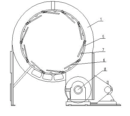
[0010] like figure 1 , figure 2 As shown, the rotary dryer includes: a cylindrical cylinder 1, a feed inlet 2 arranged at one end of the cylindrical cylinder 1 and a discharge outlet 3 arranged at the other end of the cylindrical cylinder 1, the cylindrical cylinder The two ends of 1 are respectively supported obliquely on the ground by supporting wheel device 4, the position of the feed inlet 2 is higher, and the position of the discharge port 3 is lower, and an inner drum is arranged in the cylindrical cylinder 1 5. A number of stir-frying plates 6 and semicircular projections 7 are evenly arranged in the inner drum 5, and the inner drum 5 is connected with a conveying device 8 arranged on the ground.

[0011] When in use, the transmission device 8 drives the inner drum 5 to rotate at a high speed, and the materia...


PUM


Abstract

The invention discloses a rotary dryer with a good drying effect. The rotary dryer comprises a cylindrical barrel, a feed port formed at one end of the cylindrical barrel, and a discharge port formed at the other end of the cylindrical barrel, wherein the two ends of the cylindrical barrel are obliquely supported on ground by riding wheel devices; the feed port is higher while the discharge port is lower; the cylindrical barrel is internally provided with an inner rotating drum; the inner rotating drum is internally and uniformity provided with a plurality of roasting plates and semicircular bumps; and the inner rotating drum is connected with a conveyer arranged on the ground. The rotary dryer has the advantages that the roasting platesroastmaterials; the semicircular bumps can increase friction between the materials and the inner rotating drum; and the rotary dryer is good in drying effect, simple in structure and convenient to use, and can meet requirements on drying the clammy materials of coal slurry, sludge and chemical engineering tailings.

Description

technical field [0001] The invention relates to a dryer, in particular to a rotary dryer. Background technique [0002] The drying operation of sticky and wet materials such as coal slime, sludge and chemical tailings will use the rotary dryer. The structure of the existing rotary dryer includes: a cylindrical cylinder body, a feed port arranged at one end of the cylindrical cylinder body and a discharge port arranged at the other end of the cylindrical cylinder body, and the two ends of the cylindrical cylinder body are respectively It is supported obliquely on the ground by a supporting wheel device, and an inner drum is arranged in the cylindrical cylinder, and a number of frying plates are uniformly arranged in the inner drum, and the inner drum is connected with a transmission device arranged on the ground. In the process of drying and conveying the materials, the friction between the materials and the inner drum is small, the drying and conveying effect is not good, a...

Claims


Application Information

Patent Timeline
IPC IPC(8): F26B11/06
Inventor 刘天水
Owner JIANGSU SINOMA ENVIRONMENTAL ENG
Why Eureka
Eureka Blog
Learn More