Full-liquid-phase fluid uniform distribution device of high-pressure wound-tube type heat exchanger

A coiled tube heat exchanger, high pressure technology, applied in the direction of heat exchanger shell, heat exchange equipment, lighting and heating equipment, etc., can solve the problem of uneven distribution of fluid, and achieve the goal of improving heat transfer performance and heat transfer performance Effect

Inactive Publication Date: 2013-06-12
牛玉振
View PDF4 Cites 8 Cited by
  • Summary
  • Abstract
  • Description
  • Claims
  • Application Information

AI Technical Summary

Problems solved by technology

[0003] The technical problem to be solved by the present invention is to provide a uniform distribution device for the full liquid phase flow of the coiled heat exchanger with simple structure, convenient use and high heat transfer efficiency for the uneven distribution of fluid in the shell side.

Method used


Image

  • Full-liquid-phase fluid uniform distribution device of high-pressure wound-tube type heat exchanger
  • Full-liquid-phase fluid uniform distribution device of high-pressure wound-tube type heat exchanger

Examples


Embodiment 1

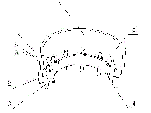
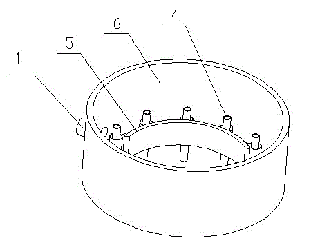
[0011] The all-liquid phase fluid uniform distribution device of the high-pressure wound tube heat exchanger includes a shell 6 and a central tube 5. The receiving plate is welded between the shell and the central tube. The shell above the receiving plate is provided with a connecting pipe 1. There are at least two vertically arranged heat exchange tubes 4 between the central tube and the shell. A shell side is formed between the shell and the heat exchange tubes. The liquid receiving plate is welded with a cofferdam tube sleeved on the heat exchange tubes. 2. The upper end of the cofferdam pipe is horizontal, and each cofferdam pipe is on a horizontal surface. The fluid enters the shell side after passing through the connecting pipe 1, passing through the annular gap bearing surface formed by the cofferdam tube and the outer wall of the heat exchange tube. The point A of the connection pipe 1 is the liquid inlet. The liquid is evenly distributed on the liquid receiving plate. ...

Embodiment 2

[0013] The all-liquid phase fluid uniform distribution device of the high-pressure wound tube heat exchanger includes a shell 6 and a central tube 5. The receiving plate is welded between the shell and the central tube. The shell above the receiving plate is provided with a connecting pipe 1. There are at least two vertically arranged heat exchange tubes 4 between the central tube and the shell. A shell side is formed between the shell and the heat exchange tubes. The liquid receiving plate is welded with a cofferdam tube sleeved on the heat exchange tubes. 2. The upper end of the cofferdam pipe is horizontal, and each cofferdam pipe is on a horizontal surface. The fluid enters the shell side after passing through the connecting pipe 1, passing through the annular gap bearing surface formed by the cofferdam tube and the outer wall of the heat exchange tube. The point A of the connection pipe 1 is the liquid inlet. The liquid is evenly distributed on the liquid receiving plate. ...

Embodiment 3

[0015] The all-liquid phase fluid uniform distribution device of the high-pressure wound tube heat exchanger includes a shell 6 and a central tube 5. The receiving plate is welded between the shell and the central tube. The shell above the receiving plate is provided with a connecting pipe 1. There are at least two vertically arranged heat exchange tubes 4 between the central tube and the shell. A shell side is formed between the shell and the heat exchange tubes. The liquid receiving plate is welded with a cofferdam tube sleeved on the heat exchange tubes. 2. The upper end of the cofferdam pipe is horizontal, and each cofferdam pipe is on a horizontal surface. The fluid enters the shell side after passing through the connecting pipe 1, passing through the annular gap bearing surface formed by the cofferdam tube and the outer wall of the heat exchange tube. The point A of the connection pipe 1 is the liquid inlet. The liquid is evenly distributed on the liquid receiving plate. ...


PUM


Abstract

The invention discloses a full-liquid-phase fluid uniform distribution device of a high-pressure wound-tube type heat exchanger The full-liquid-phase fluid uniform distribution device comprises a shell and a central cylinder, wherein a liquid receiving disk is welded between the shell and the central cylinder, a connection pipe is arranged outside the shell above the liquid receiving disk, at least two vertical heat-exchange pipes are arranged between the shell and the central cylinder, a liquid-enclosing weir pipe sleeved on the heat-exchange pipes is welded on the liquid receiving disk, and the upper end face of the liquid-enclosing weir pipe is horizontal. As the absolute horizontalness of a liquid disk can hardly be guaranteed when equipment is installed, with the liquid-enclosing weir pipe, a horizontal plane is provided to the liquid, liquid on the liquid-enclosing weir pipe can flow downwards along the walls of the heat-exchange pipes and along an annular space so as to form a uniform liquid film, and thus, the heat-transfer performance is improved. According to the full-liquid-phase fluid uniform distribution device disclosed by the invention, the problem of nonuniform distribution of a shell-pass full liquid phase of a large high-pressure wound-tube type heat exchanger is solved, and the full-liquid-phase fluid flows in a uniform distribution manner in the shell pass, so that the wound-tube type heat exchanger is greatly improved in heat-transfer performance.

Description

Technical field [0001] The invention relates to a shell-side fluid distribution structure used on a large-scale high-pressure wound tube heat exchanger, in particular to a shell-side fluid whose feed is all liquid and gas-liquid. Background technique [0002] In the world, energy demand is increasing. Natural gas purification, liquefaction, and hydrocarbon recovery devices require a large number of high-pressure wound tube heat exchangers. Now domestic large-scale wound tube heat exchangers for large-scale natural gas (LNG) liquefaction are being designed and Manufacturing research and development. A single piece of these equipment can reach a diameter of more than 7 meters and weigh about 350 tons. The fluid is unevenly distributed in the equipment. The uneven flow formed by the uneven distribution of the fluid on the shell side will greatly reduce the performance of the entire heat exchanger. This is also a design difficulty for large-scale high-pressure wound tube heat exchan...

Claims


Application Information

Patent Timeline
IPC IPC(8): F28F9/22
Inventor 牛玉振刘景武
Owner 牛玉振
Why Eureka
Try Eureka