
Selected area electron diffraction spectrum and image processing method for determining preferred orientation degree of pyrolytic carbon

An electron diffraction and preferred orientation technology, applied in image data processing, image analysis, instruments, etc., can solve the problems of easy introduction of human error and cumbersome work.

Inactive Publication Date: 2013-06-12
HANGZHOU DIANZI UNIV
View PDF0 Cites 1 Cited by
  • Summary
  • Abstract
  • Description
  • Claims
  • Application Information

AI Technical Summary

Problems solved by technology

[0004] In the past X-ray diffraction experiments, the diffraction rings were picked up by the film, and the diffraction intensity could only be measured point by point manually. Measuring just got easier
However, due to the lack of research on pyrolytic carbon materials at home and abroad, there are even fewer studies on the preferred orientation angle of pyrolytic carbon. As a result, there is currently no professional tool for determining the orientation angle, and some foreign authors use customized software to measure Orientation angle

Method used


Image

  • Selected area electron diffraction spectrum and image processing method for determining preferred orientation degree of pyrolytic carbon
  • Selected area electron diffraction spectrum and image processing method for determining preferred orientation degree of pyrolytic carbon
  • Selected area electron diffraction spectrum and image processing method for determining preferred orientation degree of pyrolytic carbon

Examples


Embodiment Construction

[0037] Further illustrate the present invention below in conjunction with accompanying drawing.

[0038] The selected area electron diffraction pattern image processing method of the present invention determines the preferred orientation degree of pyrolytic carbon comprising the following steps:

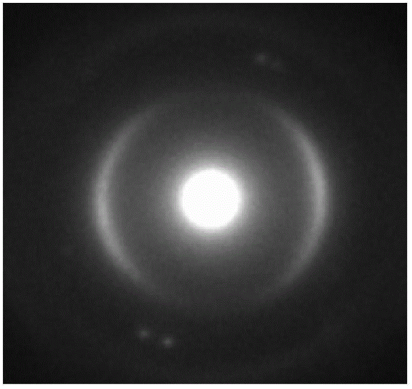
[0039] Step 1: If figure 1 , figure 2 As shown, the electron diffraction pattern of the original selected area is binarized, the binarization threshold is set to 50, and the (002) diffraction ring and its internal area with a brightness value greater than or equal to 50 are selected, and the selected area is the bright area.

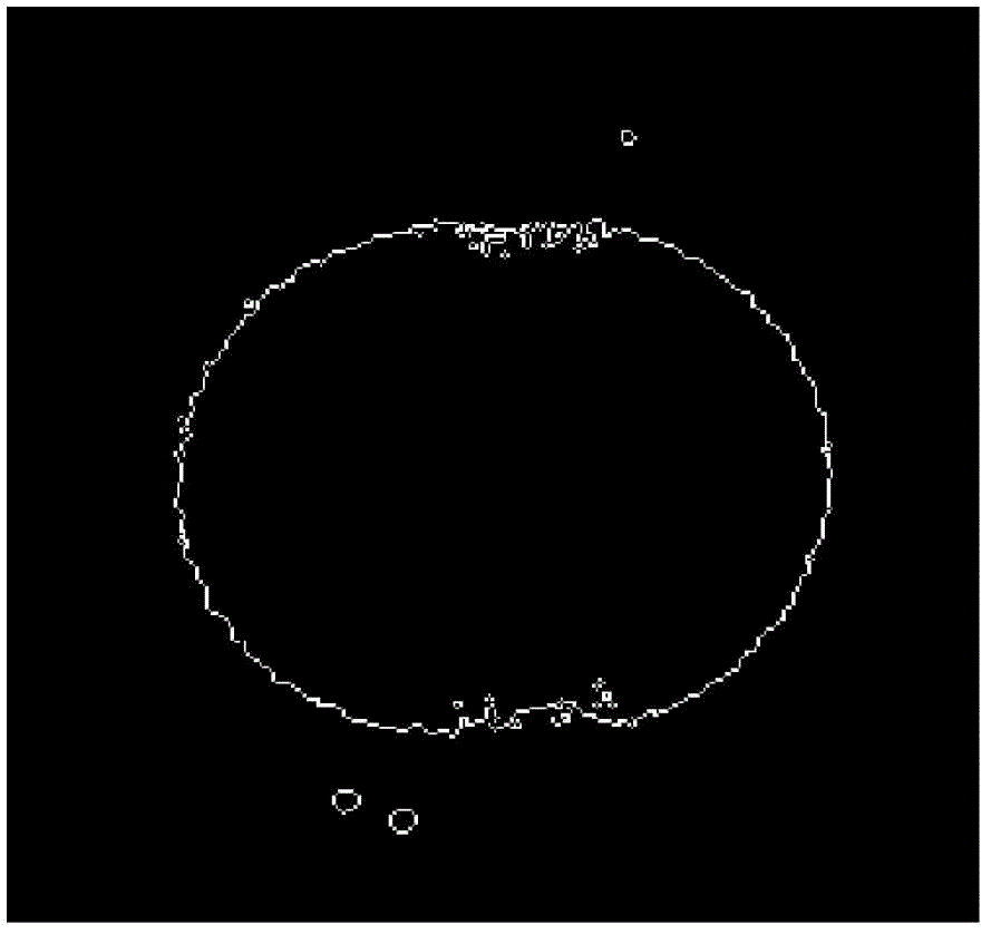
[0040] Step 2: If image 3 As shown in , the image obtained by binarization processing is edged, the boundary of the bright area is determined, the boundary point is taken, and the center and radius of the circle are fitted according to the least square method, and the value is (002) the approximate center of the diffraction ring ( , ) with radius R....


PUM


Abstract

The invention discloses a selected area electron diffraction pattern and image processing method for determining preferred orientation degree of pyrolytic carbon. The method comprises the following steps that binarization processing is performed on an original pattern, a diffraction ring and an inner area of the diffraction ring, a brightness value of which is greater than or equal to 50, is selected, and marginalized processing is performed; bright area boundaries are determined, a least square method is used for fitting a center of a circle and a radius, and an approximate center of the circle and an approximate radius of the diffraction ring are obtained; according to the approximate center of the circle and the approximate radius, a small radius of a circular area is 0.7 times the approximate radius, and a large radius of the circular area is 1.2 times the approximate radius; an inner area and an outer area of the diffraction ring are deducted, then the binarization processing is performed again, a part, the brightness value of which is greater than or equal to 145, is selected from the circular area, i.e. the diffraction ring; and according to the least square method, the center of the circle and the radius of the diffraction ring are fitted again, pattern sampling points are determined, and a strength-azimuth curve is obtained to determine the preferred orientation degree of the pyrolytic carbon. By using the method, the strength-azimuth curve of a pyrolytic carbon coating can be simply, conveniently and accurately obtained, so as to determine the preferred orientation degree of the pyrolytic carbon.

Description

technical field [0001] The invention relates to a selected area electron diffraction spectrum image processing method for determining the preferred orientation degree of pyrolytic carbon, in particular to a selected area electron diffraction spectrum image processing method for determining the preferred orientation degree of an artificial heart valve silicon-containing pyrolytic carbon coating. Background technique [0002] Pyrolytic carbon coatings prepared by fluidized-bed chemical vapor deposition (CVD) are prone to preferential orientation during deposition. The preferred orientation is related to the deposition process and deposition conditions, and also affects the structure and properties of the pyrolytic carbon coating. By preparing pyrolytic carbon with different preferred orientations, different material performance requirements can be met. For artificial heart valve pyrolytic carbon coatings, it is required to be high-density isotropic pyrolytic carbon. Theref...

Claims


Application Information

Patent Timeline
IPC IPC(8): G06T7/00
Inventor 张建辉韦静杨欢李学鹏钟华锋孙海博
Owner HANGZHOU DIANZI UNIV
Learn More