
Optical module and adaptive regulation method for rate mode of clock and data recovery (CDR) chip of optical module

A rate mode and optical module technology, applied in the direction of electromagnetic transmitters, etc., can solve the problems that the signal cannot be locked, the signal cannot be shaped, and the signal cannot be shaped to ensure the quality of the signal, so as to achieve the effect of ensuring the signal quality

Inactive Publication Date: 2013-06-12
HISENSE BROADBAND MULTIMEDIA TECH
View PDF5 Cites 17 Cited by
  • Summary
  • Abstract
  • Description
  • Claims
  • Application Information

AI Technical Summary

Problems solved by technology

The CDR chip is usually fixed to a preset rate mode after the optical module is initially powered on; as a result, the CDR chip cannot lock signals with a rate beyond the processing capability of the preset rate mode, and cannot These signals are shaped to ensure signal quality
[0013] To sum up, the optical modules in the prior art cannot shape a signal with a wide rate range to ensure signal quality, and do not have better compatibility with various transmission protocols

Method used


Image

  • Optical module and adaptive regulation method for rate mode of clock and data recovery (CDR) chip of optical module
  • Optical module and adaptive regulation method for rate mode of clock and data recovery (CDR) chip of optical module
  • Optical module and adaptive regulation method for rate mode of clock and data recovery (CDR) chip of optical module

Examples


Embodiment Construction

[0048] In order to make the object, technical solution and advantages of the present invention clearer, the present invention will be described in further detail below with reference to the accompanying drawings and preferred embodiments. However, it should be noted that many of the details listed in the specification are only for readers to have a thorough understanding of one or more aspects of the present invention, and these aspects of the present invention can be implemented even without these specific details.

[0049] As used herein, terms such as "module" and "system" are intended to include computer-related entities such as, but not limited to, hardware, firmware, a combination of hardware and software, software, or software in execution. For example, a module may be, but is not limited to being limited to being, a process running on a processor, a processor, an object, an executable, a thread of execution, a program, and / or a computer.

[0050] The inventors of the p...


PUM


Abstract

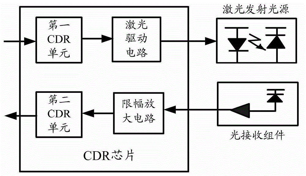
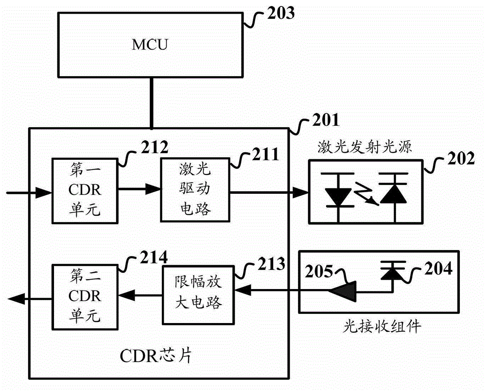
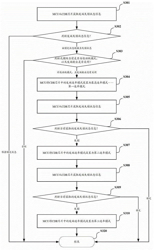
The invention discloses an optical module and an adaptive regulation method for the rate mode of a clock and data recovery (CDR) chip of the optical module. The optical module comprises the CDR chip, a laser emission light source and a microprogrammed control unit (MCU), wherein the CDR chip integrates a laser driving circuit and a first CDR unit; the first CDR unit locks a received electric signal according to the set initiative rate mode, shapes the electric signal and outputs the shaped electric signal to the laser driving circuit to drive the laser emission light source to emit laser; and the and MCU regulates the initiative rate mode of the CDR chip according to initiative unlock state information acquired from the CDR chip. The MCU in the optical module acquires the unlock state information, which serves as feedback information, from the CDR chip, and the rate mode in the CDR chip is adaptively regulated, so that the CDR chip can regulate to have the rate mode suitable for locking signals at the current rate according to the current signal rate, and shape signals in a wider rate range to ensure signal quality.

Description

technical field [0001] The invention relates to optical fiber communication technology, in particular to an optical module and a method for adaptively adjusting the rate mode of a CDR chip. Background technique [0002] In the current domestic market and international market, the optical fiber communication direction of high bandwidth, high speed and multi-service integration has begun to be applied; among many solutions, the emergence of fiber-to-the-home (FTTH) is considered to be the ultimate broadband access solution. The domestic market has been widely used. [0003] Among the many FTTH solutions, PON (passive optical network) has attracted much attention and has become the mainstream optical access method; among them, the ten-gigabit passive optical network has been widely used. XFP (10Gigabit Small Form Factor Pluggable, 10G small package pluggable optical module) optical module is the core component of the 10-gigabit passive optical network, installed in OLT or ONU...

Claims


Application Information

Patent Timeline
IPC IPC(8): H04B10/50
Inventor 陈彪
Owner HISENSE BROADBAND MULTIMEDIA TECH
Learn More