Multi-base sonar space-time channel multiplexing method

A channel multiplexing, multi-base technology, applied in multiplexing communication, orthogonal multiplexing systems, electrical components, etc., can solve the problem of limited frequency band resources, complex received signal composition, and impossible to talk about positioning optimization algorithms and other problems to achieve the effect of improving time, efficient reuse, and reducing cross-correlation

Active Publication Date: 2013-06-12
HARBIN ENG UNIV
View PDF3 Cites 11 Cited by
  • Summary
  • Abstract
  • Description
  • Claims
  • Application Information

AI Technical Summary

Problems solved by technology

In the European patent "Method for the multistatic detection and locating of a mobile craft through the use of digital broadcasting transmitters", it is proposed that each transmitter of the multi-base station adopts signals of different carrier frequencies in order to distinguish them at the receiver. However, for multi-base For sonar systems, the frequency band resources are limited, so that this method can only be applied in the case of a small number of transmitters. At the same time, the patent also involves how to distinguish detection signals from different transmission times
In the application of multi-mode and multi-base sonar, the composition of the received signal at the receiving end at a certain moment is very complex, including direct waves and target echoes from different transmitting ends in space and at different transmitting times in time. If the space-time information of the received signal cannot be obtained, the ranging and direction finding of the target cannot be realized, let alone the positioning optimization algorithm.

Method used


Image

  • Multi-base sonar space-time channel multiplexing method
  • Multi-base sonar space-time channel multiplexing method
  • Multi-base sonar space-time channel multiplexing method

Examples


Embodiment Construction

[0025] The present invention will be specifically described below in conjunction with the accompanying drawings.

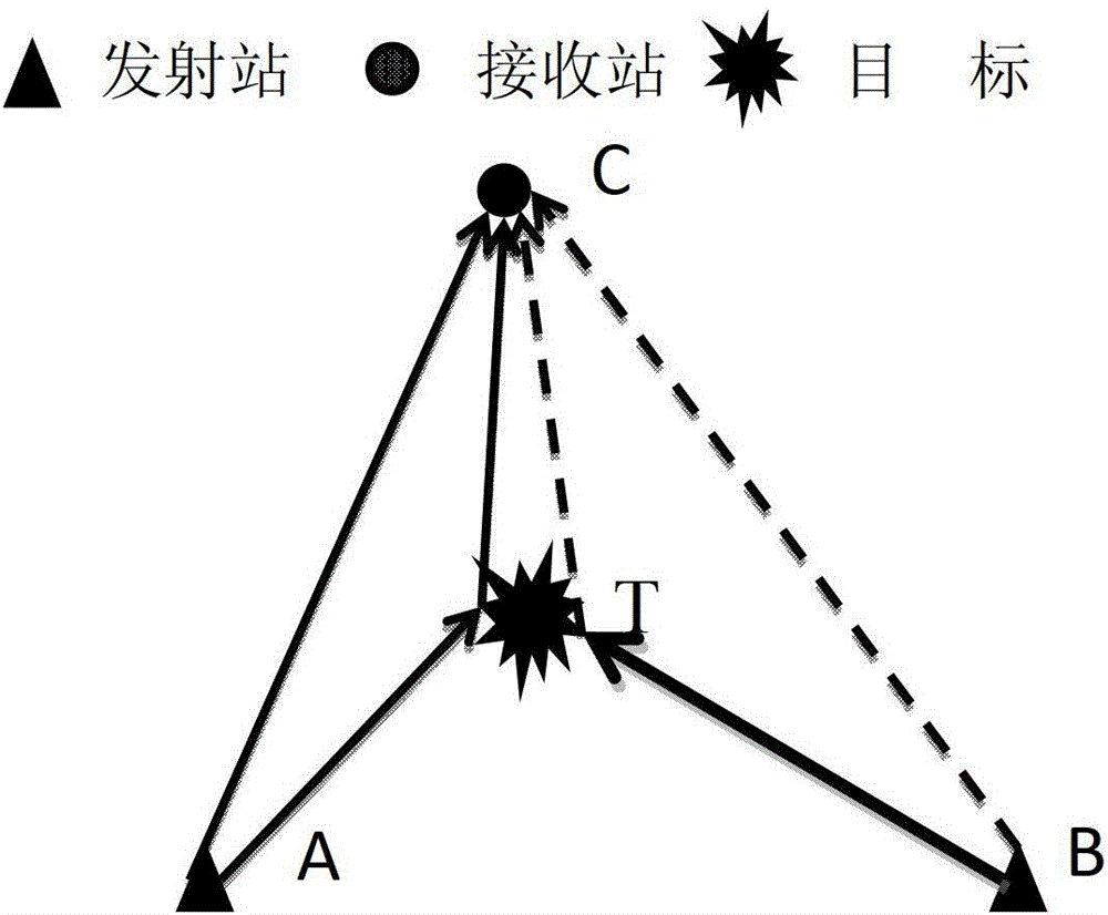
[0026] A multi-base sonar space-time channel multiplexing method provided by the present invention includes two parts: signal design at the transmitting end and signal processing at the receiving end:

[0027] The transmitting end:

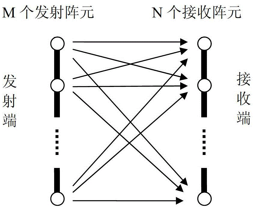
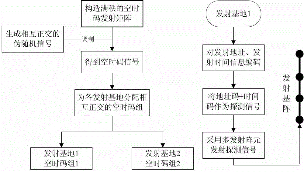
[0028] Step 1. Modulate a full-rank space-time code matrix with mutually orthogonal pseudo-random signals to obtain space-time code signals based on pseudo-random modulation.

[0029] Step 2. Allocate independent and mutually orthogonal space-time code groups for each transmitting end of the multi-base system as a codebook for transmitting signals of each transmitting end.

[0030] Step 3. Encode the transmission address and transmission time of each transmission at the transmitting end, and use the form of address code + time code as the signal structure of the detection signal, and the detection signal is transmitted through the tr...


PUM


Abstract

The invention relates to the field of processing of a sonar signal, and particularly relates to a multi-base sonar space-time channel multiplexing method. The method comprises the following steps of obtaining a space-time code signal modulated in a pseudo random way; distributing independent and mutually orthogonal space-time code groups for transmitting terminals of a multi-base system; encoding the transmitting address and transmitting time of each transmitting signal; copying the related detection on the received signal, and distinguishing whether the detection signal of the corresponding transmitting terminal is contained in the received signal; extracting a time code, and using the space-time signal code of the corresponding base to carry out maximum likelihood decoding; and obtaining the information of the transmitting address and the transmitting time of the detection signal, namely the space-time information. The method has the advantages that the correlation between code elements of the space-time code is reduced, the high-efficiency multiplexing of the multi-base sonar space-time channel is realized by the accurate evaluation of the space-time information of any received signal, the time of the multi-base sonar system is improved, and the utilization rate of frequency bands is improved.

Description

technical field [0001] The invention relates to the field of sonar signal processing, in particular to a multi-base sonar space-time channel multiplexing method. Background technique [0002] Multi-base sonar is a sonar system with spatially separated transceiver devices. Single or multiple sound sources emit sound waves, and single or multiple receivers receive the scattered echoes of the target. By measuring the reflection direction and time delay of the target echo, the multi-base sonar Direction and ranging, and then solve the target position through the positional relationship between the transceiver equipment and the sonar positioning equation. According to the number of sending and receiving devices, multi-base sonar can be divided into several types: one sending and multiple receiving, multiple sending and one receiving, and multiple sending and multiple receiving. Multi-base sonar combines the working characteristics of active and passive sonar, and has the advanta...

Claims


Application Information

Patent Timeline
Patent Type & Authority Applications(China)
IPC IPC(8): H04L1/06H04J11/00
Inventor 生雪莉芦嘉董伟佳郭龙祥殷敬伟
Owner HARBIN ENG UNIV
Why Eureka
Try Eureka