Thyristor LED (Light Emitting Diode) light adjusting circuit and mixed reference control method thereof
A dimming circuit and control method technology, applied in the direction of lamp circuit layout, light source, electric light source, etc., can solve the problems of reducing the efficiency of LED lighting system, increasing the difficulty of heat dissipation of LED drive circuit, increasing cost, etc., achieving high power factor and ensuring Stable triggering and improved conversion efficiency
- Summary
- Abstract
- Description
- Claims
- Application Information
AI Technical Summary
Problems solved by technology
Method used
Image
Examples
specific Embodiment 1
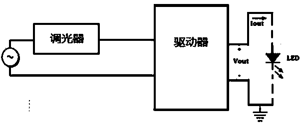
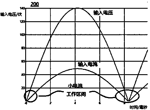
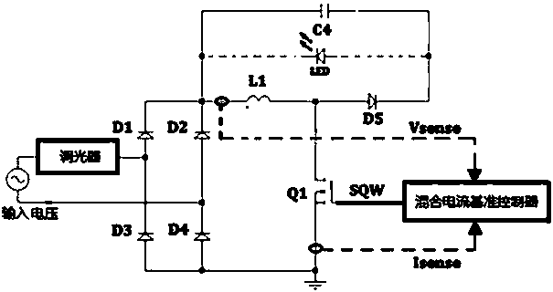
[0038] Specific embodiment 1: Using 2 voltage reference values to obtain 3 sets of current reference combinations, setting the inductor current reference from the three perspectives of improving power factor, maintaining stable triggering of thyristor, and driving circuit efficiency requirements, specifically includes the following steps:
[0039] Step 1. Collect the instantaneous value Vsense of the input voltage of the drive circuit in the thyristor LED dimming circuit and the instantaneous current value Isense that flows through the switch after the switch is turned on.
[0040] Step 2: Compare the instantaneous value Vsense of the input voltage of the drive circuit with the first reference value of the input voltage:
[0041] When the instantaneous value Vsense of the input voltage of the drive circuit is lower than the first reference value of the input voltage, a straight line whose amplitude is beneficial to maintain the steady triggering of the thyristor is used as the induc...
specific Embodiment 2
[0053] Specific embodiment 2: Using 1 voltage reference value to obtain 2 sets of current reference combinations, setting the inductor current reference from the two perspectives of increasing the power factor and maintaining the stable triggering of the thyristor, specifically includes the following steps:
[0054] Step 1. Collect the instantaneous value Vsense of the input voltage of the drive circuit in the thyristor LED dimming circuit and the instantaneous current value Isense that flows through the switch after the switch is turned on.
[0055] Step 2: Compare the instantaneous value Vsense of the input voltage of the drive circuit with the first reference value of the input voltage:
[0056] When the instantaneous value Vsense of the input voltage of the drive circuit is lower than the first reference value of the input voltage, a straight line whose amplitude is beneficial to maintain the steady triggering of the thyristor is used as the inductor current reference;
[0057] Whe...
specific Embodiment 3
[0065] Specific embodiment 3: Using 1 voltage reference value to obtain 2 sets of current reference combinations, setting the inductor current reference from the two perspectives of improving the efficiency of the drive circuit and maintaining the stable triggering of the thyristor, specifically includes the following steps:
[0066] Step 1. Collect the instantaneous value Vsense of the input voltage of the drive circuit in the thyristor LED dimming circuit and the instantaneous current value Isense that flows through the switch after the switch is turned on.
[0067] Step 2: Compare the instantaneous value Vsense of the input voltage of the drive circuit with the first reference value of the input voltage:
[0068] When the instantaneous value Vsense of the input voltage of the drive circuit is lower than the first reference value of the input voltage, a straight line whose amplitude is beneficial to maintain the steady triggering of the thyristor is used as the inductor current ref...
PUM
 Abstract
Description
Claims
Application Information
 - R&D
- Intellectual Property
- Life Sciences
- Materials
- Tech Scout
- Unparalleled Data Quality
- Higher Quality Content
- 60% Fewer Hallucinations
Browse by: Latest US Patents, China's latest patents, Technical Efficacy Thesaurus, Application Domain, Technology Topic, Popular Technical Reports.
© 2025 PatSnap. All rights reserved.Legal|Privacy policy|Modern Slavery Act Transparency Statement|Sitemap|About US| Contact US: help@patsnap.com


