
LED (light emitting diode) driving power supply with high power factor and without electrolytic capacity

A high-power-factor, LED-driven technology, used in electric light sources, lamp circuit layout, and high-efficiency power electronic conversion, etc., can solve the problem that the performance of driving power is limited by power factor and cannot be matched with long-life LEDs, and achieve high power factor. Effect

Inactive Publication Date: 2013-06-12
NANJING UNIV OF AERONAUTICS & ASTRONAUTICS
View PDF4 Cites 17 Cited by
  • Summary
  • Abstract
  • Description
  • Claims
  • Application Information

AI Technical Summary

Problems solved by technology

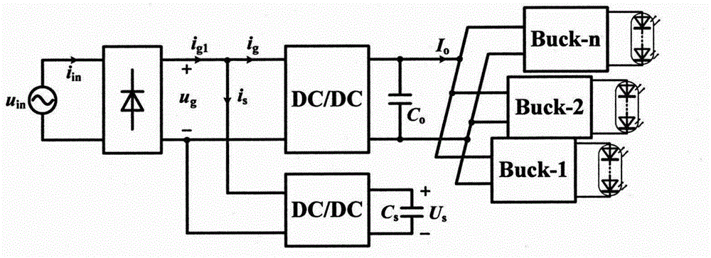
[0007] In order to overcome the serious defect that the traditional LED driving power supply cannot match the long-life LED due to the use of electrolytic capacitors and solve the problem that the performance of the driving power supply is limited by the power factor, this invention provides a new solution that not only does not require electrolytic capacitors, but also High power factor electrolytic capacitor LED drive power supply capable of compensating power factor

Method used


Image

  • LED (light emitting diode) driving power supply with high power factor and without electrolytic capacity
  • LED (light emitting diode) driving power supply with high power factor and without electrolytic capacity
  • LED (light emitting diode) driving power supply with high power factor and without electrolytic capacity

Examples


Embodiment Construction

[0028] Below in conjunction with accompanying drawing and specific embodiment, further illustrate the present invention, should be understood that these specific embodiments are only for illustrating the present invention and are not intended to limit the scope of the present invention, after having read the present invention, those skilled in the art will understand each aspect of the present invention The modifications in equivalent forms and the structure block diagram of the LED driving power supply similar to the present invention all fall within the scope defined by the appended claims of the present application.

[0029] In order to understand the content of the present invention and facilitate analysis and description, make following assumptions:

[0030] 1. All devices are ideal devices without any loss;

[0031] 2. The switching frequency is much higher than the fundamental frequency of the power supply, and the high-order harmonics caused by the switching tube actio...


PUM


Abstract

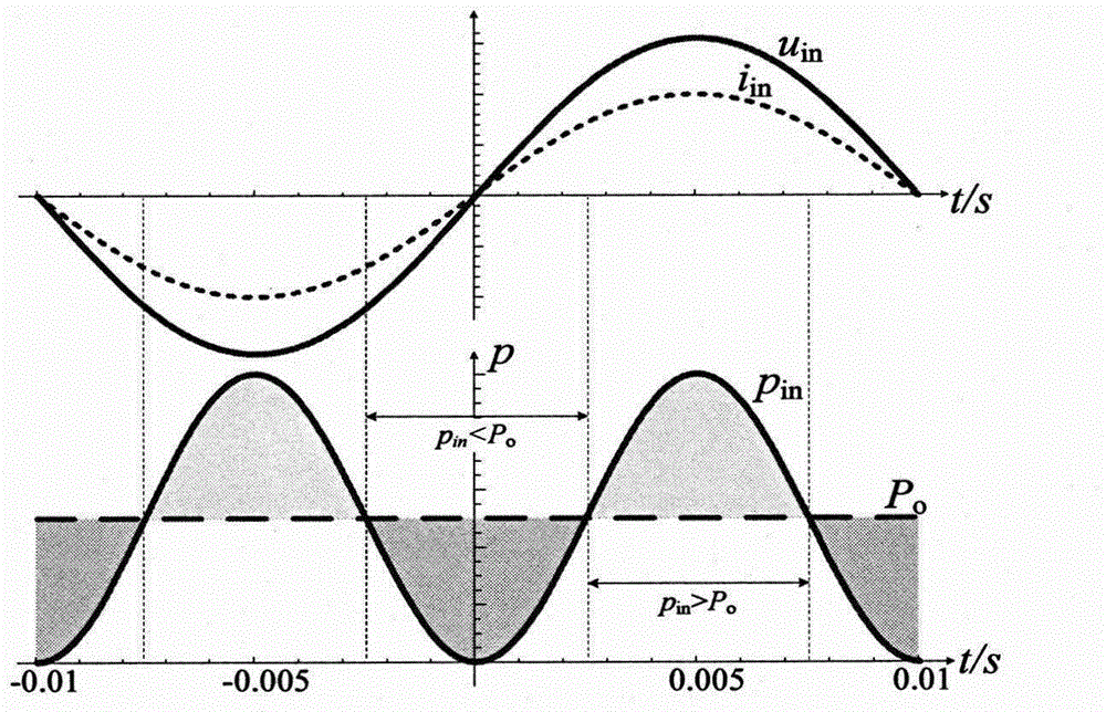
The invention relates to an LED (light emitting diode) driving power supply with a high power factor and without electrolytic capacity. The LED driving power supply mainly comprises an alternating current input power supply, a monophase uncontrolled rectifier bridge, a main DC (direct current) / DC conversion circuit, an auxiliary DC / DC conversion circuit, an energy storage capacitor and a filter capacitor. The LED driving power supply is mainly and technically characterized in that the auxiliary DC / DC conversion circuit is merged into the input end of the main DC / DC conversion circuit, and has the functions of balancing an instantaneous power between input and output to be without the electrolytic capacity and compensating a current wave shape on the input end to realize the high power factor. By the adoption of the driving power supply, the defect that a three-time harmonic wave injection method is limited by the power factor is made up, and a method of double frequency current wave shape fitting can be further adopted, thus the acquisition of a reference current wave shape is further simplified, and the controlling is facilitated. As a voltage ripple on the energy storage capacitor has no requirement, needed capacity values of the energy storage capacitor and the filter capacitor are extremely small, a film capacitor or a ceramic capacitor and the like can be directly adopted, the driving power supply has the advantages of long service life and the like, and is suitable for places of a public driving power supply of an LED with large power.

Description

technical field [0001] The invention relates to a high power factor LED driving power supply without an electrolytic capacitor, and belongs to the technical field of AC-DC converters in electric energy conversion devices. Background technique [0002] Light-emitting diode (Lighting Emitting Diode, LED) is a solid-state cold light source. It has the advantages of high efficiency, energy saving, environmental protection, long life, small size, safety, and fast response. It has become a new generation of green lighting source. With the development of LED body and driving power technology, it has been widely used in mobile phones, automobiles, landscapes, large screens, military, household lighting and other fields, and it will eliminate other lighting sources. The luminous quality of LED is determined by its average current and peak-to-average ratio. Therefore, the performance of LED driving power supply is very important, and the key is to manufacture high-efficiency, high pow...

Claims


Application Information

Patent Timeline
Patent Type & Authority Applications(China)
IPC IPC(8): H05B37/02H02M1/12H02M1/42
CPCY02B70/10
Inventor 文教普秦海鸿聂新
Owner NANJING UNIV OF AERONAUTICS & ASTRONAUTICS
Learn More