Method and control and tracking system of the charge of material transported by a continuous supply conveyor of a metallurgical furnace, particularly an electric furnace for the production of steel

A technology for conveyors and metallurgical furnaces, used in conveyor control devices, conveyor objects, transportation and packaging, etc., can solve the problems of not allowing evaluation, not allowing to find out the type of charge, etc.

Active Publication Date: 2013-06-12
ТЕНОВА ТЕКНОЛОДЖИЗ (ТЯНЬЦЗИНЬ) КО., ЛТД.
View PDF11 Cites 9 Cited by
  • Summary
  • Abstract
  • Description
  • Claims
  • Application Information

AI Technical Summary

Problems solved by technology

[0015] However, the method and control equipment described in US 6,004,504 do not allow to find out the type (quality / composition) of charge gradually fed to the furnace; Intervening in the reception of the melt

Method used


Image

  • Method and control and tracking system of the charge of material transported by a continuous supply conveyor of a metallurgical furnace, particularly an electric furnace for the production of steel
  • Method and control and tracking system of the charge of material transported by a continuous supply conveyor of a metallurgical furnace, particularly an electric furnace for the production of steel
  • Method and control and tracking system of the charge of material transported by a continuous supply conveyor of a metallurgical furnace, particularly an electric furnace for the production of steel

Examples


Embodiment Construction

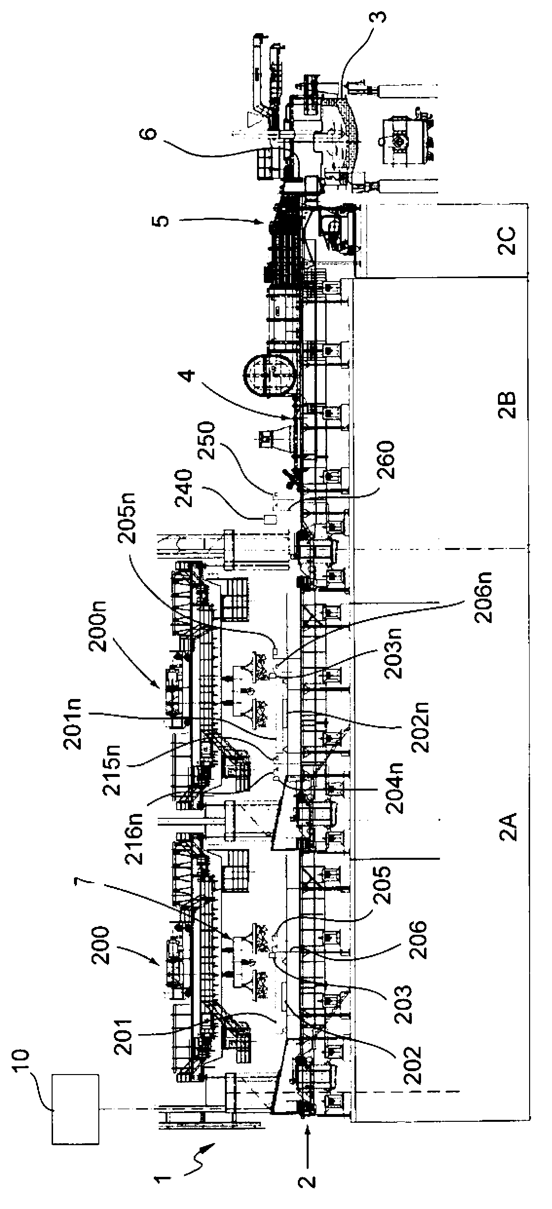
[0027] Referring to the drawings, there is shown a control and tracking system 1 for charge material transported by a continuous feed conveyor 2 for feeding a metallurgical furnace 3, in particular an electric furnace for steel production.

[0028] The furnace 3 is preferably, but not exclusively, of the arc type, but it may also be of the induction or plasma type.

[0029] The conveyor 2 is preferably, but not exclusively, of the vibratory type, but it may also be of the belt type or similar.

[0030] The conveyor 2, starting from its inlet end towards its outlet end, successively comprises a loading section 2A of the charge material to be fed to the furnace 3, a preheating section 2B of the loaded charge material and the entry of the preheated charge material into the furnace Introduced subsection 2C in 3.

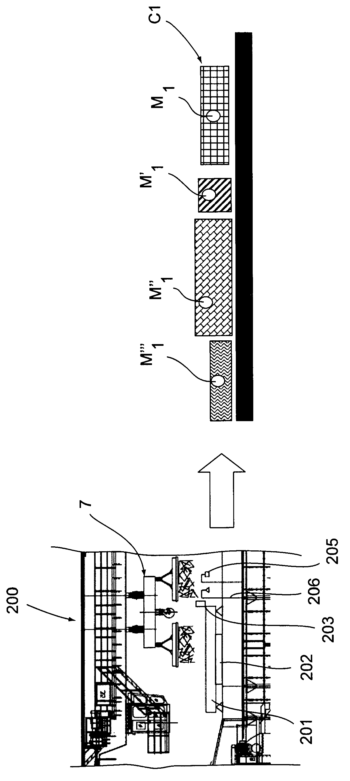
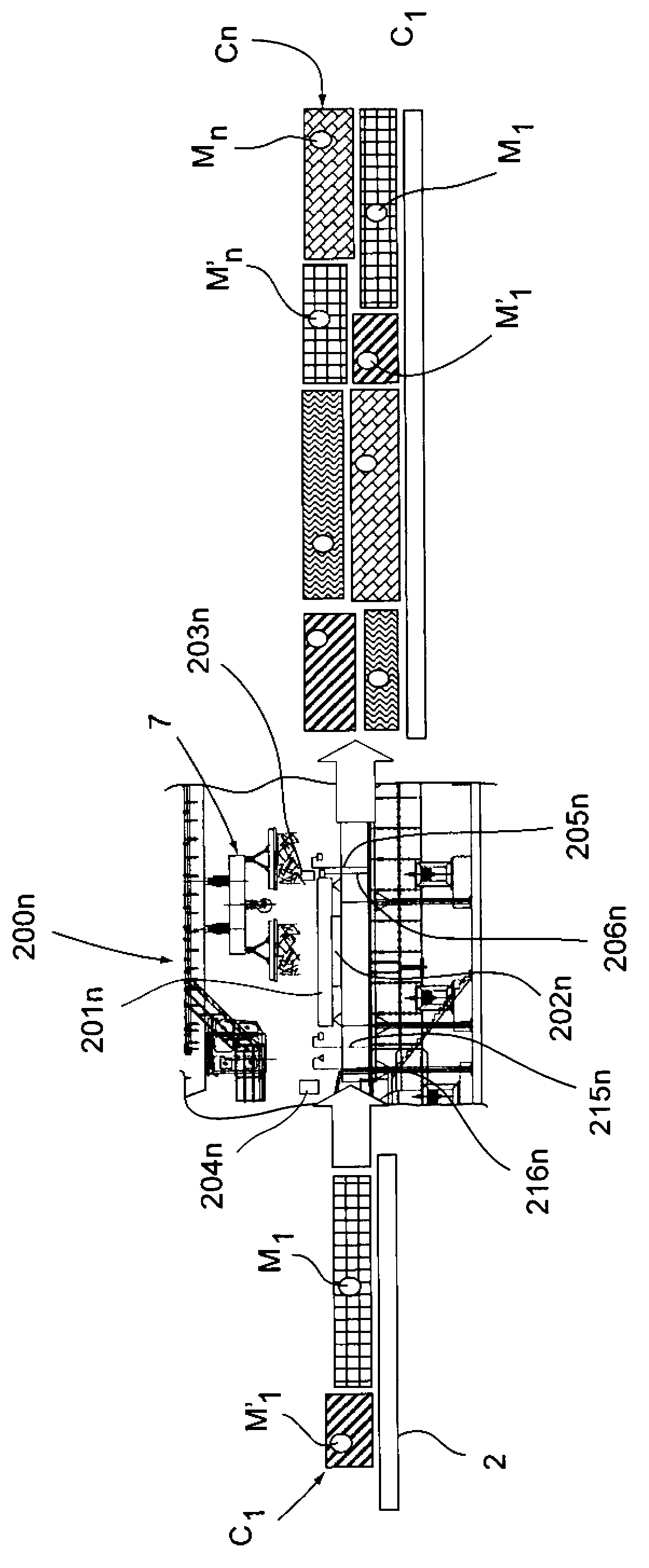
[0031] Along the loading section 2A there is provided at least a first loading station 200 of material, followed by one or more subsequent nth loading stations 200n.

...


PUM


Abstract

The present invention refers to a method and to a control and tracking system of the charge of material transported by a continuous supply conveyor (2) of a metallurgical furnace (3), in particular an electric furnace for the production of steel, wherein said continuous conveyor (2) comprises, in sequence starting from its inlet end towards its outlet end, a loading section (2A) of the charge of material to be supplied to said furnace (3), a preheating section (2B) of the charge of material loaded and an introduction section (2C) into said furnace (3) of the preheated charge of material, and wherein along said loading section (2A) at least a first loading station (200) of material is present, wherein the method comprises the steps consisting in determining (101) the type and the weight of the material of a first charge fraction to be loaded into the first loading station (200); in function of a predetermined charge recipe (100), supplying (102) the first loading station (200) with the first charge fraction, detecting (103) the weight of the first charge fraction, discharging (104) the first charge fraction (C1) onto the continuous conveyor (2), marking (105) the first charge fraction (C1) through identification means (M1, M1', M1''), detecting (106) the overall dimensions of the first charge fraction (C1) discharged onto the continuous conveyor (2), estimating (107, 108) the advancing speed of the first charge fraction (C1) along the loading section (2A) of the continuous conveyor (2) and the arrival time of the first charge fraction (C1) entering a possibly subsequent loading station (200n) of a further charge fraction or the preheating section (2B), and, in proximity to the inlet of the preheating section (2B), recognising (115).

Description

technical field [0001] The present invention relates to a method and a control and tracking system for the transport of charge material by a continuous feed conveyor of a metallurgical furnace, in particular an electric furnace for steel production. Background technique [0002] The technology for producing steel through the use of Electric Arc Furnaces (EAF) is well established, starting from charge mixtures that include different types of materials in different proportions (iron material, reduced iron, scrap iron / steel, etc.) , these ratios depend on the type and quality of steel desired. [0003] The supply of charge material to the furnace may be of the discontinuous or continuous type. [0004] KR100685049 to Posco, US4,579,524 to GN Kinematics Corp and EP0526664 to Sibag Schmid Industrieberatung each describe an apparatus for feeding charge material to a metallurgical furnace in a discontinuous manner and a method for controlling the charge material The relevant syst...

Claims


Application Information

Patent Timeline
Patent Type & Authority Applications(China)
IPC IPC(8): F27B3/18F27B3/28F27D13/00F27D19/00F27D21/00B65G43/08C21C5/52
CPCC21C5/527C21C2005/5282C21C2005/5288F27B3/18F27B3/28F27D13/002F27D19/00F27D21/0035B65G43/08F27D13/00F27D21/00C21C5/52Y02P10/20
Inventor F·A·M·阿桑特R·吉雷利S·M·雷亚利
Owner ТЕНОВА ТЕКНОЛОДЖИЗ (ТЯНЬЦЗИНЬ) КО., ЛТД.
Why Eureka
Try Eureka