Car lamp steering system driving device

A technology of steering system and driving device, which is applied in signal devices, vehicle parts, transportation and packaging, etc., and can solve problems such as poor stability of movement displacement and large degree of shaking

Active Publication Date: 2013-06-19
TRICORE CORP
View PDF7 Cites 3 Cited by
  • Summary
  • Abstract
  • Description
  • Claims
  • Application Information

AI Technical Summary

Problems solved by technology

[0003] Because the linear moving screw moves axially through the nut part of the motor magnet axis, and uses the rectangular hole positioning of the motor casing to perform linear movement, but the linear moving s

Method used


Image

  • Car lamp steering system driving device
  • Car lamp steering system driving device
  • Car lamp steering system driving device

Examples


Embodiment Construction

[0018] The structure and effect of the present invention will be described in detail by citing the following embodiments in conjunction with the accompanying drawings.

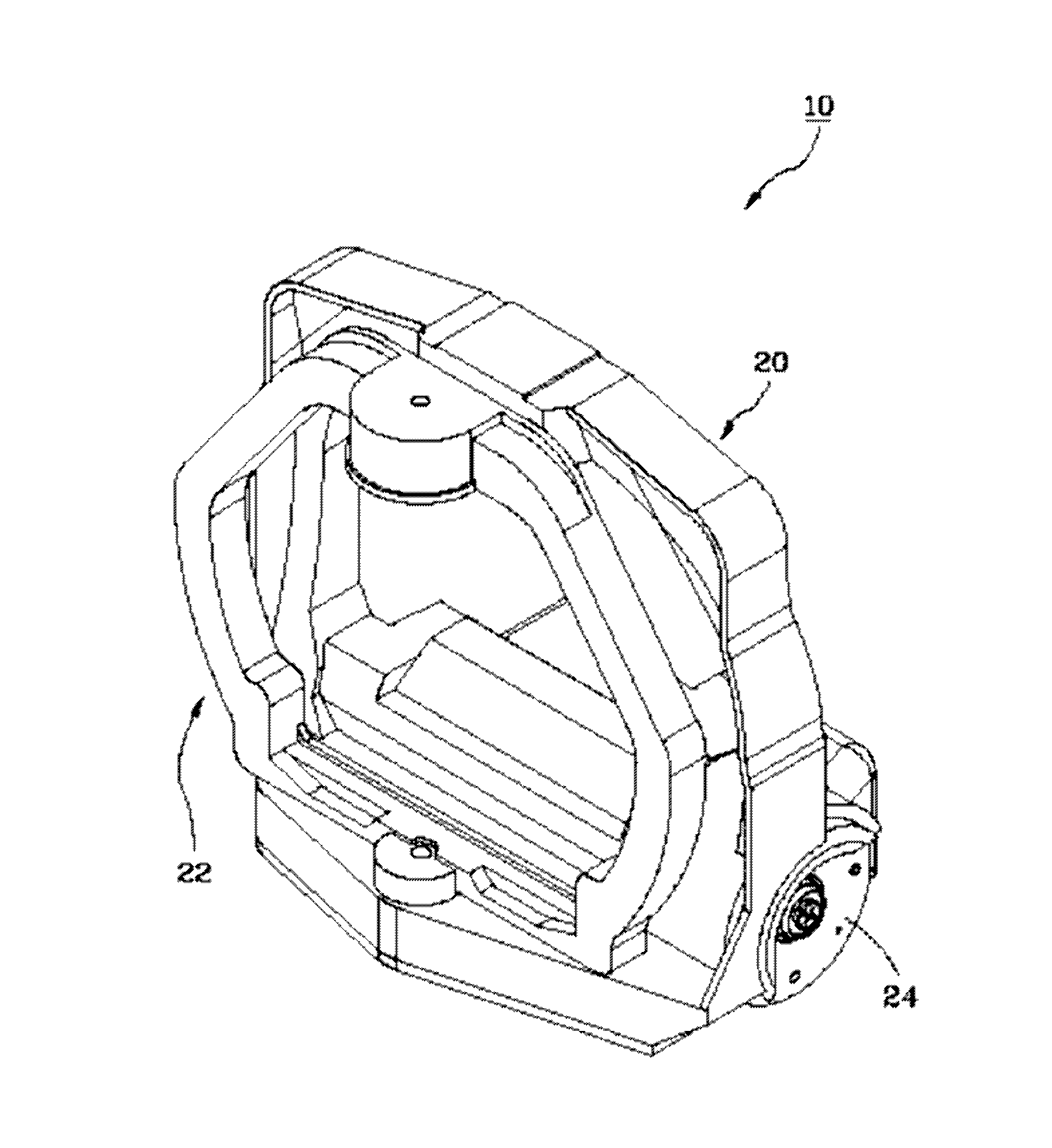
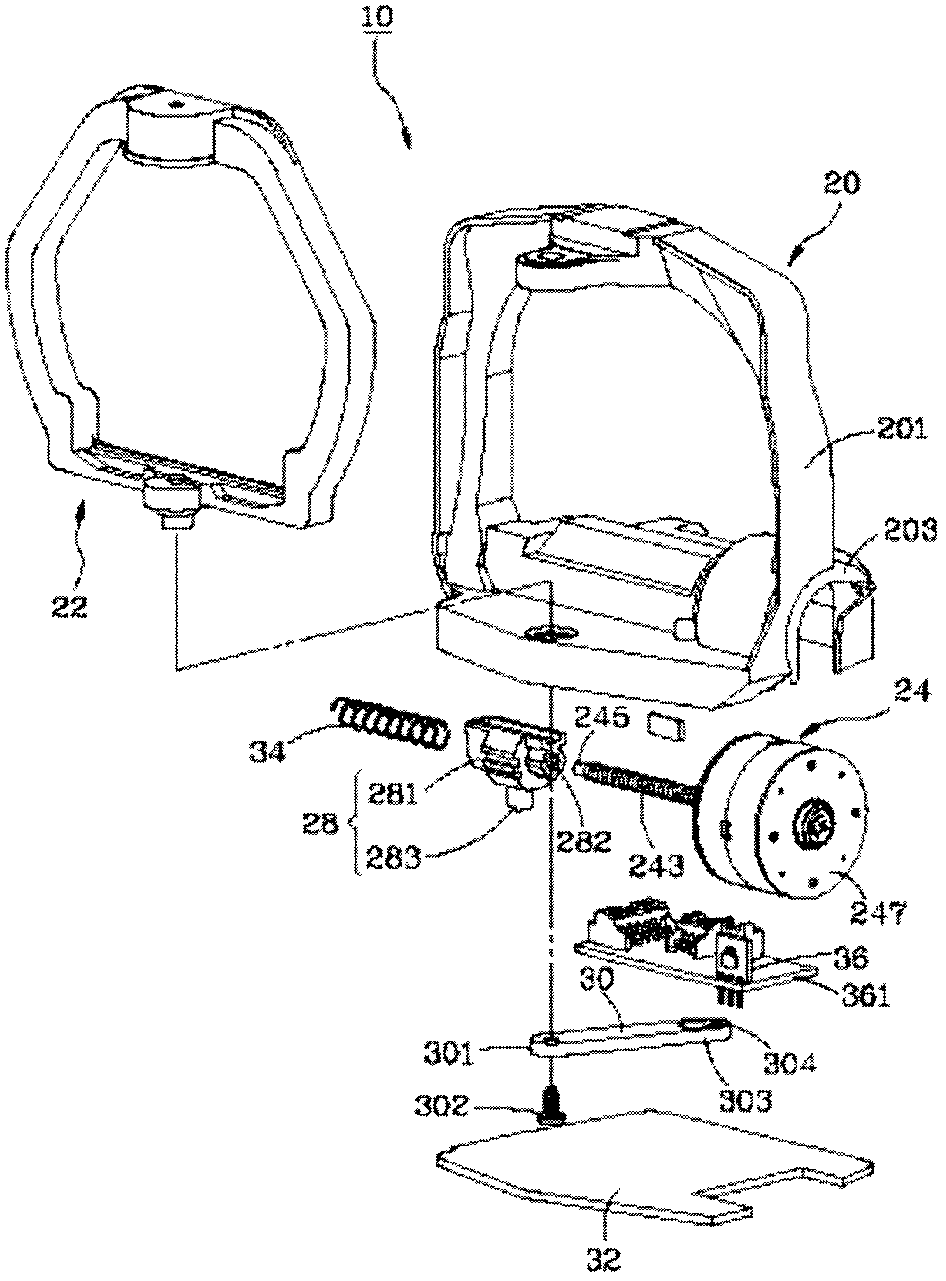
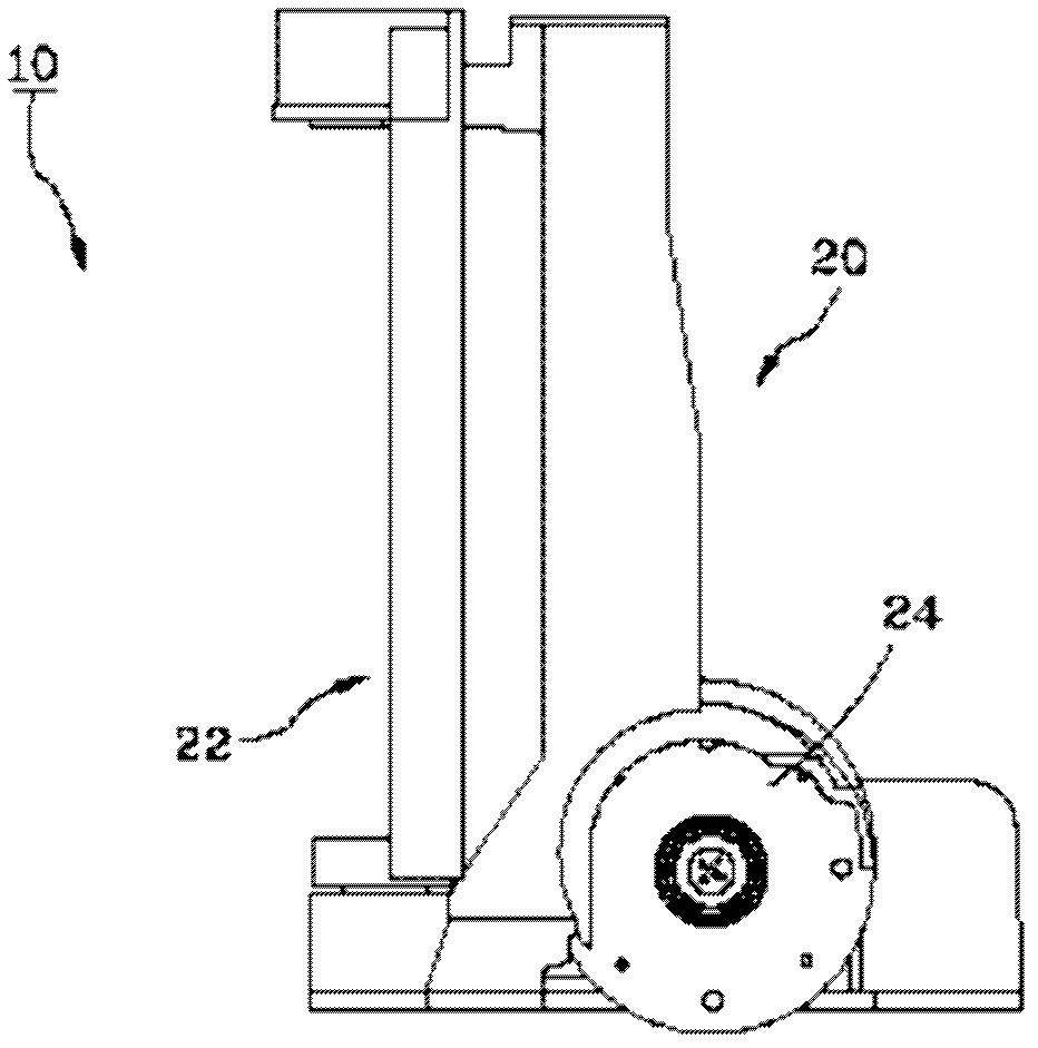
[0019] Such as Figure 1 to Figure 4 As shown, the vehicle light steering system driving device 10 provided by the first preferred embodiment of the present invention includes a base 20, a lamp support base 22, a stepping motor assembly 24, a moving part 28, a rotating rocker arm 30, A bottom cover 32 , a spring 34 and a position sensing component 36 .

[0020] The base 20 includes a frame portion 201, a motor accommodating portion 203 and a supporting portion 205 (such as Figure 4 As shown), the motor accommodating portion 203 and the supporting portion 205 are located at the bottom side of the frame portion 201 , and the supporting portion 205 has a fixing hole 206 .

[0021] The lamp support base 22 is pivotally connected to the frame portion 201 of the base 20 for setting a vehicle lamp (not shown in th...


PUM


Abstract

The invention relates to a car lamp steering system driving device. The car lamp steering system driving device is characterized by comprising a base, a lamp support, a stepper motor assembly, a movable piece and a rotating rocker arm. The lamp support is connected with the base in a pivot mode, the stepper motor assembly is arranged on the base and provided with an output screw shaft, the output screw shaft can rotate but can not move along the axial direction, the movable piece is provided with a main body and a connecting part, the main body is meshed with the output screw shaft, the rotating rocker arm is provided with a first end and a second end, the first end is fixed on a lamp support, and the second end is connected with the connecting part of the movable piece. Due to the fact that the output screw shaft of the stepper motor assembly is transmitted in a rotating movement mode and fixed on a supporting part on the base, and thus the moving stability of the movable piece is greatly improved.

Description

technical field [0001] The invention relates to a headlight capable of changing the irradiation angle, in particular to a driving device for a car light steering system driven by a stepping motor to achieve the adjustment effect. Background technique [0002] The known driving device for the steering system of the vehicle lights, such as the structure disclosed in US Patent No. 7,223,001, includes a headlight support and a linear actuator, which is used to drive the headlight support deflection, and includes a motor (motor), a linear-movement screw (linear-movement screw) and a set of components (coupling part), the linear-movement screw is connected between the motor and the component, and has a The cavity is used for inserting the coupling end of the headlamp support base. Thus, when the screw rod is driven by the motor to move axially, the assembly part can drive the headlight support base to rotate, so as to achieve the purpose of adjusting the irradiation direction of ...

Claims


Application Information

Patent Timeline
IPC IPC(8): B60Q1/12B60Q1/076
Inventor 辜婷怡
Owner TRICORE CORP
Why Eureka
Try Eureka