Variable trailing edge wing driven by combination of shape memory alloy and piezoelectric fibrous composite material

A piezoelectric fiber and composite material technology, applied in the field of morphing wings, can solve the problems of slow response speed and small driving force, and achieve the effects of large deformation range, stable operation and simple structure

Active Publication Date: 2013-06-19
HARBIN INST OF TECH
View PDF4 Cites 39 Cited by
  • Summary
  • Abstract
  • Description
  • Claims
  • Application Information

AI Technical Summary

Problems solved by technology

[0004] The purpose of the present invention is to solve the problem of slow driving response speed and small driving force of MFC driven by SMA alone, and then provide a variable trailing edge wing driven by a combination of shape memory alloy and piezoelectric fiber composite material

Method used


Image

  • Variable trailing edge wing driven by combination of shape memory alloy and piezoelectric fibrous composite material
  • Variable trailing edge wing driven by combination of shape memory alloy and piezoelectric fibrous composite material
  • Variable trailing edge wing driven by combination of shape memory alloy and piezoelectric fibrous composite material

Examples


specific Embodiment approach 1

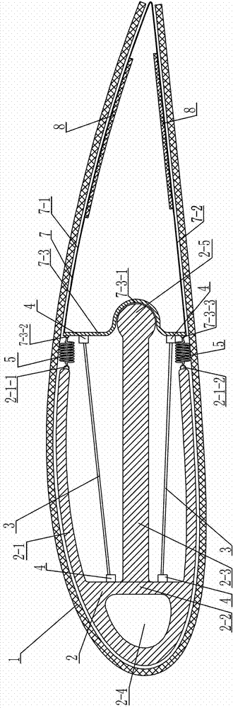
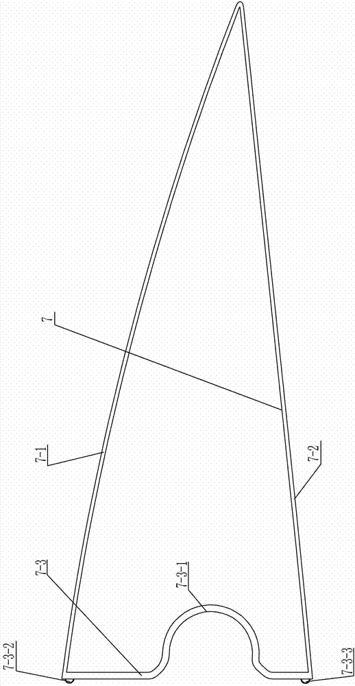
[0008] Specific implementation mode one: combine figure 1 Describe this embodiment. A variable trailing edge wing driven by a combination of shape memory alloy and piezoelectric fiber composite material in this embodiment includes a skin 1, a fixed part 2, a movable part 7, and at least a pair of shape memory alloy wires 3. At least one pair of elastic parts 5 and at least one pair of piezoelectric fiber composite materials 8, the fixed part 2 is connected to the movable part 7 through at least one pair of elastic parts 5, and at least one pair of shape Memory alloy wire 3, the two ends of at least one pair of shape memory alloy wire 3 are respectively connected with the fixed part 2 and the movable part 7, the movable part 7 can rotate around the fixed part 2, and the skin 1 is wrapped around the fixed part 2 and the movable part 7 On the outer surface, the movable part 7 includes an upper plate 7-1, a lower plate 7-2 and a connecting plate 7-3, and the upper plate 7-1, the l...

specific Embodiment approach 2

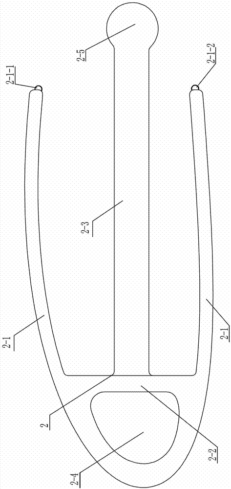
[0010] Specific implementation mode two: combination figure 1 and 2 Describe this embodiment, the fixture 2 in this embodiment includes an arc-shaped plate 2-1 and a vertical plate 2-2, the front end of the arc-shaped plate 2-1 is connected with a vertical plate 2-2, the vertical plate 2-2 and A through hole 2-4 is formed between the curved plates 2-1. Such arrangement facilitates the fixed connection with the aircraft body. The other specific embodiments are the same.

specific Embodiment approach 3

[0011] Specific implementation mode three: combination figure 1 and figure 2 To illustrate this embodiment, the fixing member 2 in this embodiment also includes a flat plate 2-3, a flat plate 2-3 is connected to the vertical plate 2-2, and the end of the flat plate 2-3 has a cylindrical boss 2-5, The middle part of the connecting plate 7-3 has a concave surface 7-3-1 matching the side of the cylindrical boss 2-5, and the side of the cylindrical boss 2-5 is attached to the concave surface 7-3-1 of the connecting plate 7-3. 1 on. With such arrangement, the design is reasonable and the structure is simple. When the SMA is driven, it can effectively realize that the movable part 7 can rotate around the fixed part 2, which is convenient and reliable. Others are the same as in the second embodiment.


PUM


Abstract

The invention discloses a variable trailing edge wing driven by combination of a shape memory alloy and a piezoelectric fibrous composite material, and relates to a variable trailing edge version wing driven by two different drivers. The problems that when an SMA (shape memory alloy) is used for driving, the response speed is slow, and when an MFC (fibrous composite material) is used for driving, the driving force driven is small are solved. The variable trailing edge wing comprises a skin, a fixing piece, a moving piece, at least one pair of shape memory alloy wires, at least one pair of elastic parts and at least one pair of piezoelectric fibrous composite materials, wherein the fixing piece is connected with the moving piece through the at least one pair of flexible assemblies, the at least one pair of shape memory alloy wires are arranged between the at least one pair of elastic parts, the at least one pair of shape memory alloy wires are respectively connected with the fixing piece and the moving piece, the moving piece can rotate through rolling the fixing piece, the skin is coated on the outer surfaces of the fixing piece and the moving piece, the moving piece comprises an upper plate, a lower plate and a connecting plate, and the upper plate, the lower plate and the connecting plate are connected into a whole and is of a ring-shaped structure. The variable trailing edge wing provided by the invention is used for manufacturing the wings on airplanes.

Description

technical field [0001] The invention relates to a variant wing with a variable trailing edge driven by two kinds of drivers, which belongs to the field of variant aircraft. Background technique [0002] Since the invention of the aircraft, how to improve the aerodynamic performance of the aircraft has always been one of the important research contents of aircraft designers. The wings of current fixed-wing aircraft extend outward from the fuselage at a fixed angle and are strong enough to fly without significant movement or twisting, although it has leading and trailing edge flaps to improve flight efficiency. The aerodynamic operating part itself is still a rigid surface, and it is difficult to change the characteristics of the wing according to the flight conditions during flight, and the aerodynamic efficiency of the aircraft wing cannot be optimized. However, bird wings in nature can be subtly adjusted according to the needs of flight at any time, achieving amazing high ...

Claims


Application Information

Patent Timeline
Patent Type & Authority Applications(China)
IPC IPC(8): B64C3/38B64C3/26
Inventor 李承泽尹维龙王长国李建军
Owner HARBIN INST OF TECH
Why Eureka
Try Eureka