
Microelectromechanical system comprising a beam that undergoes flexural deformation

a micro-electromechanical system and beam technology, applied in the field of micro-electromechanical systems or mems, can solve the problem of rapid deformation and achieve the effect of high deformation rate and simple production

Inactive Publication Date: 2007-02-15
STMICROELECTRONICS SRL +1
View PDF6 Cites 8 Cited by
  • Summary
  • Abstract
  • Description
  • Claims
  • Application Information

AI Technical Summary

Benefits of technology

[0010] An embodiment of the present invention provides a microelectromechanical system that is both simple to produce and has high deformation rates.
[0013] The thickness of at least one of the flat faces may for example be less that one quarter the external dimension of the cross section. Such a beam possesses a relatively low weight, so that, when it deforms, it exhibits little inertia, while still maintaining a high stiffness. Its deformations are therefore rapid.
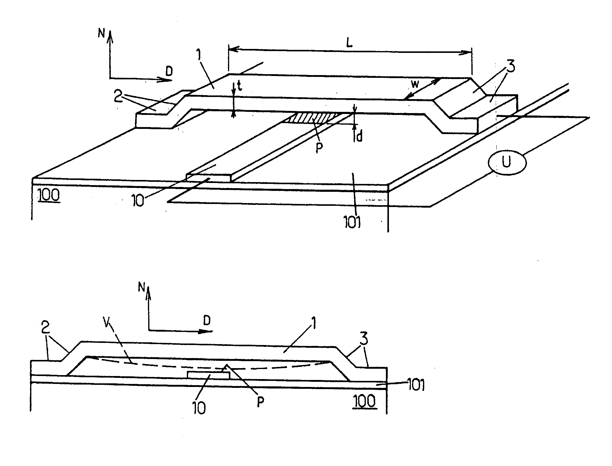
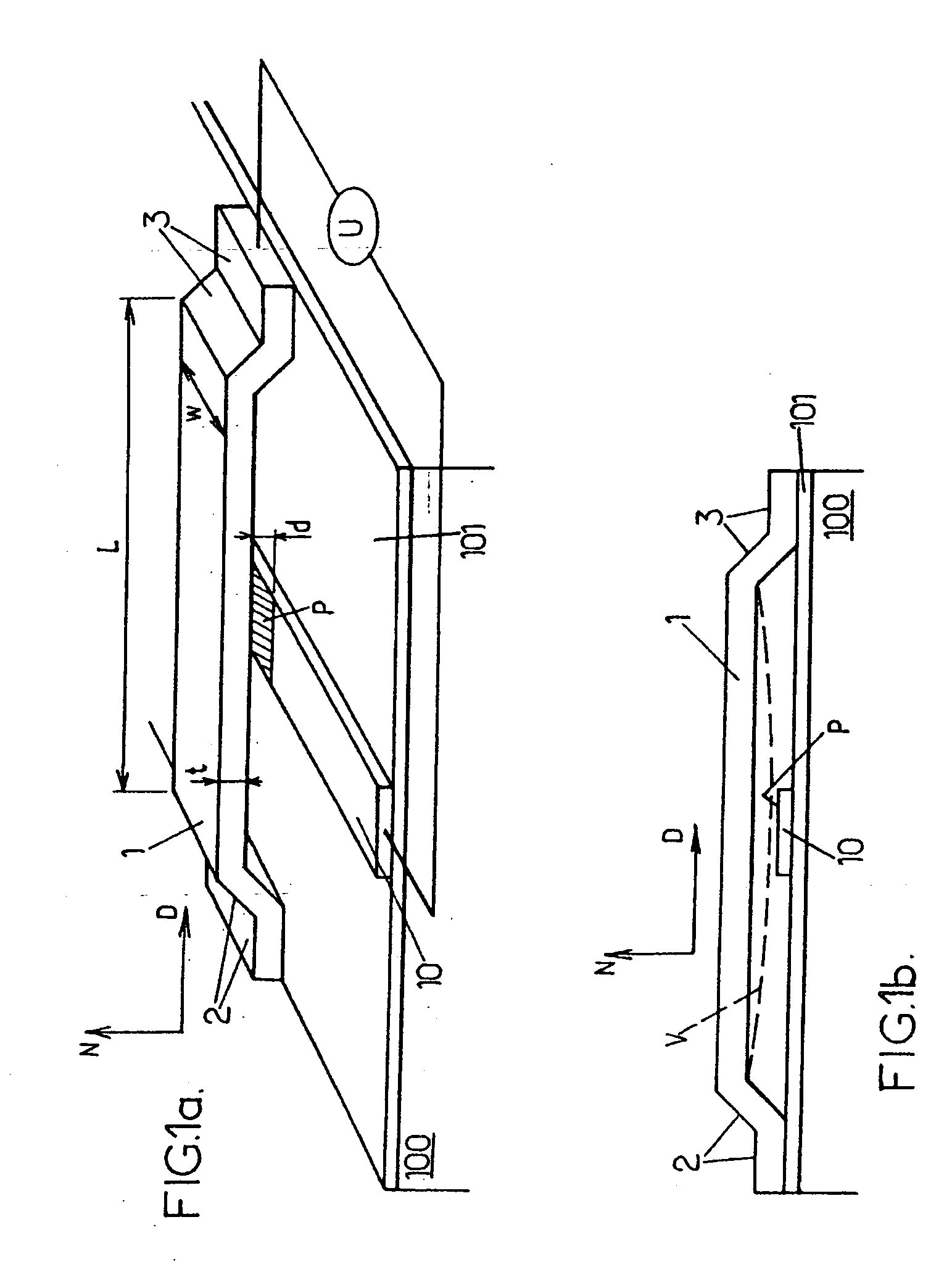
[0015] One advantage of a microelectromechanical system according to some embodiments of the invention stems from the fact that the beam undergoes flexural deformation. Given that the flexural deformations of the beam may have a large amplitude, the beam and the electrode can nevertheless be fabricated easily, without requiring high precision in the respective dimensions and locations of the beam and of the electrode.
[0022] Such a process may be particularly simple to implement when the cross section of the beam is a closed cross section, of square or rectangular external shape, formed by four pairwise perpendicular flat faces, or when the cross section is of U or H shape. This is because the beam may then be produced by combining masking steps, for masking specified parts of the microelectromechanical system, material deposition steps and etching steps that are simple and well-controlled. Such steps may for example be borrowed from the technologies used for fabricating integrated electronic circuits. In particular, the beam may advantageously be based on silicon or on a silicon-germanium alloy. This is because particularly well-controlled selective etching processes exist for these materials, allowing defined cross sections to be accurately produced.
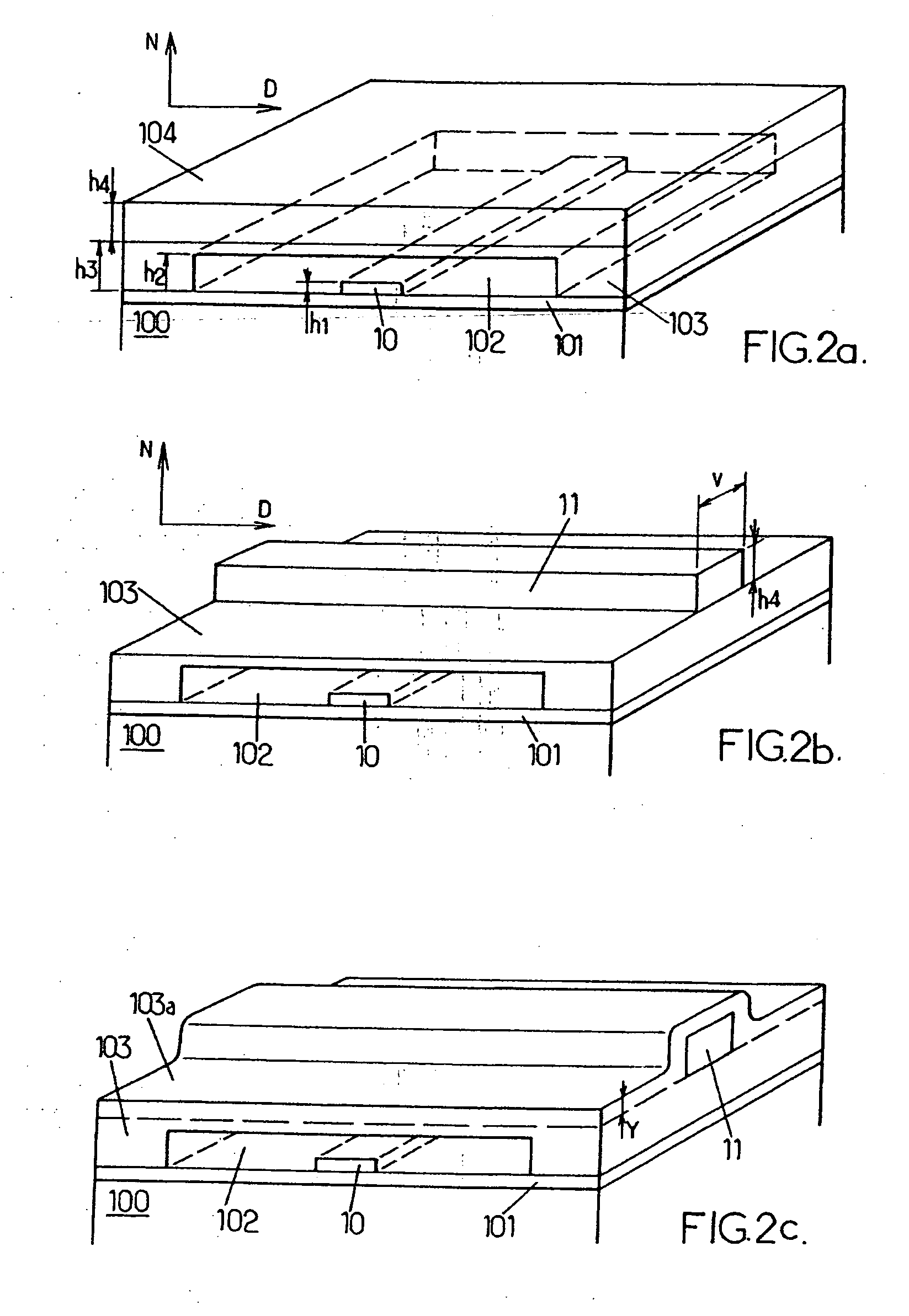
[0026] According to a second method, an elongate structure may firstly be formed, and then etched so that the flat faces consist of residual portions of the elongate structure. The process may then further include a step d) of forming a second empty space between at least two of the flat faces of the beam. In this case, steps c) and d) are preferably carried out simultaneously, especially so as to reduce the number of steps in the process for fabricating the microelectromechanical system.

Problems solved by technology

Its deformations are therefore rapid.

Method used


Image

  • Microelectromechanical system comprising a beam that undergoes flexural deformation
  • Microelectromechanical system comprising a beam that undergoes flexural deformation
  • Microelectromechanical system comprising a beam that undergoes flexural deformation

Examples


Embodiment Construction

[0033] For the sake of clarity, the various elements shown in these figures have not been drawn to scale. FIGS. 1 and 2a-2f are perspective views of a substantially plane substrate, on which a microelectromechanical system according to the invention is produced. The substrate is in the lower part of each figure, and N denotes a direction perpendicular to the surface of the substrate, directed upwards in the figures. In the rest of the description, the terms “on”, “under”, “lower” and “upper” are used with reference to this orientation. Furthermore, in all the figures, identical references correspond to identical elements.

[0034] A process for fabricating a microelectromechanical system according to the invention will now be described with reference to FIGS. 2a-2f. In this description, elementary steps of the process that are known from the fabrication of an integrated electronic circuit will not be explained in detail. Only the succession of individual steps for producing the microe...


PUM

PropertyMeasurementUnit
widthaaaaaaaaaa
thicknessaaaaaaaaaa
widthaaaaaaaaaa

Abstract

A microelectromechanical system comprises a beam and an electrode coupled to the beam via electrostatic interaction. The beam is designed to undergo elastic flexural deformation and has an approximately constant cross section. The beam consists of several flat faces that extend over the length of the beam, each having a thickness of less than an external dimension of the cross section. A flexural vibration frequency of the beam is then increased compared with a solid beam of the same external dimensions. Such a microelectromechanical system is suitable for applications requiring very short transition times, or for producing high-frequency oscillators and resonators.

Description

BACKGROUND OF THE INVENTION [0001] 1. Field of the Invention [0002] The present invention relates to a microelectromechanical system or MEMS, comprising a beam designed to undergo flexural deformation. It also relates to a process for producing such a microelectromechanical system. [0003] 2. Description of the Related Art [0004] Various microelectromechanical systems intended to be integrated into an electronic device are known. For example, the article entitled “Vibrating RF MEMS for low-power wireless communications” by Clark T.-C. Nguyen, Proceedings, 2000 Int. MEMS Workshop (iMEMS'01), Singapore, Jul. 4-6, 2001, pp. 21-34, describes microelectromechanical systems of various configurations. Among these microelectromechanical systems, some comprise a beam intended to undergo elastic flexural deformation and others comprise a volume intended to exhibit what are called elastic contour variations. The microelectromechanical systems undergoing volume contour variations exhibit particu...

Claims


Application Information

Patent Timeline
Patent Type & Authority Applications(United States)
IPC IPC(8): H01H57/00C23F1/00H02N1/00
CPCB81B3/007B81B2201/016B81B2201/0271H03H9/2463H03H3/0076H03H9/2447B81B2203/0118
Inventor CASSET, FABRICESEGUENI, KARIMDE GRAVE, ARNAUDABELE, NICOLAS
Owner STMICROELECTRONICS SRL
Learn More