Foil stamping method and corresponding device

A foil and pressure technology, which is applied in the field of foil stamping and the device used for the same, can solve the problem that it cannot be carried out on the side.

Inactive Publication Date: 2014-07-23
彼得巴特
View PDF10 Cites 5 Cited by
  • Summary
  • Abstract
  • Description
  • Claims
  • Application Information

AI Technical Summary

Problems solved by technology

A disadvantage of this method is that the thinning of the applied patt

Method used


Image

  • Foil stamping method and corresponding device

Examples


Embodiment Construction

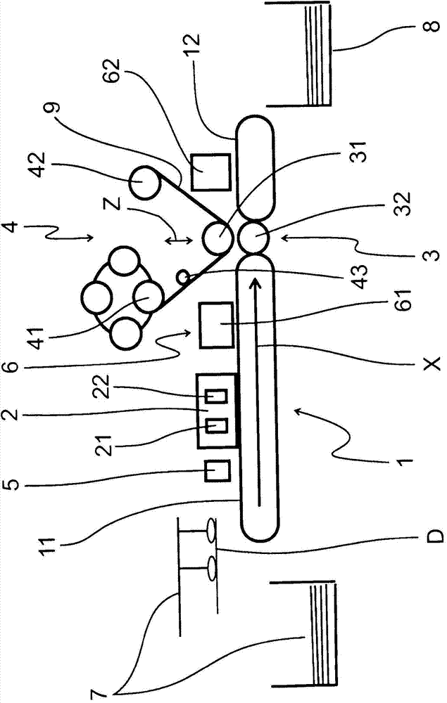
[0019] exist figure 1 A schematic diagram of the foil stamping setup is shown in . The features described next are here suitably given the figure 1 The direction of work indicated by the arrow X in the middle is discussed.

[0020] In the illustrated embodiment, individual webs are used as printed products D, that is to say printed sheets suitably cut into a defined format, which are deposited by means of a web feeder 7 to the transport mechanism 1, ie here the suction belt works on stage. The conveying mechanism 1 has a first suction belt table 11 and downstream a second suction belt table 12 .

[0021] Downstream of the abutment region of the first suction belt table 11, a printed sheet orientation device and a printed product sensor 5, for example in the form of a printed sheet leading edge and / or a printed sheet trailing edge sensor, are provided. Sheet orientators are known from printing presses or other graphics-like machines. Downstream of the printed product senso...


PUM

PropertyMeasurementUnit
Thicknessaaaaaaaaaa

Abstract

The invention relates to a foil stamping method according to which a surface of a printing product (D) is provided with an adhesive layer in places intended to be imprinted prior to a transfer film (9), which consists of a carrier film and a transfer layer adhering thereto by means of a release layer, being placed onto the printing product (D) under the effect of pressure, the transfer layer sticking to the printing product (D) in places intended to be imprinted. Prior to foil printing, an applicable adhesive is applied to the printing product (D), instead of or in addition to the adhesive layer, in the places intended to be semi-embossed and the pressure acts evenly across the entire surface of the printing product (D), namely also on the raised places resulting from semi-embossing and the remaining surroundings during foil printing. The invention further relates to a foil stamping device for transferring a transfer layer which adheres to a carrier film onto the printing product (D) in places intended to be imprinted, said foil stamping device comprising a conveying system (1) for the printing product (D), adhesive application means (2), arranged on the conveying system (1), which provides a surface of the printing product (D) with an adhesive layer in places intended to be imprinted, a foil transfer means (3) having a transfer roller (31) and a foil feeding means (4) associated with the foil transfer means (3), the outer surface of the transfer roller (31) being covered with an elastic cover of a small thickness.

Description

technical field [0001] The invention relates to a foil embossing method, in which the surface of a printed product is first provided with an adhesive layer at the location intended for printing, which then comprises a carrier foil and a foil attached to said carrier foil by means of a release layer The transfer foil of the transfer layer is placed onto the printed product under pressure, the transfer layer remaining attached to the printed product in the position provided for printing. Furthermore, the invention relates to a foil embossing device for transferring a transfer layer attached to a carrier foil onto a printed product in a position provided for printing, comprising: a transport mechanism for the printed product; An adhesive application mechanism arranged on the surface of the printed product is provided with an adhesive layer at a position set for printing; a foil transfer mechanism including a transfer roller and a foil transfer mechanism configured to Foil delive...

Claims


Application Information

Patent Timeline
IPC IPC(8): B44C1/14B44C1/17
CPCB44C1/145B44C1/1733Y10T156/1705B41F16/0033B41F19/004B41F19/062B41C1/08B41F19/001B41F19/008B41F19/06
Inventor 彼得·巴特
Owner 彼得巴特
Why Eureka
Try Eureka