
Packing box

A packaging box and box cover technology, applied in packaging, transportation and packaging, rigid containers, etc., can solve the problems of waste of resources, high production costs, large storage space, etc., and achieve the advantages of diverse combinations, enhanced fastening, and simple packaging Effect

Inactive Publication Date: 2013-06-19
黄文充
View PDF10 Cites 18 Cited by
  • Summary
  • Abstract
  • Description
  • Claims
  • Application Information

AI Technical Summary

Problems solved by technology

[0003] Existing commonly used packaging is concentrated on synthetic boards, wooden boards, gray cardboards, metal products and other packaging materials that have been laminated and laminated. These types of packaging materials have problems such as resource waste and environmental pollution to varying degrees. Disadvantages are large volume, large storage space, high transportation costs, and high production costs
[0004] Commonly used packaging boxes are manufactured at the production site and then transported to the place of use. The packaging box is bulky and the transportation cost is high
If it is made at the place of use, it is very inconvenient to make at the place of use because certain equipment and auxiliary materials are required.
Commonly used packaging boxes are generally used independently. When they need to be used in combination, they are often bundled. There is no combination method that is both beautiful and convenient without affecting the overall state and effect of the packaging box.

Method used


Image

  • Packing box
  • Packing box
  • Packing box

Examples


Embodiment Construction

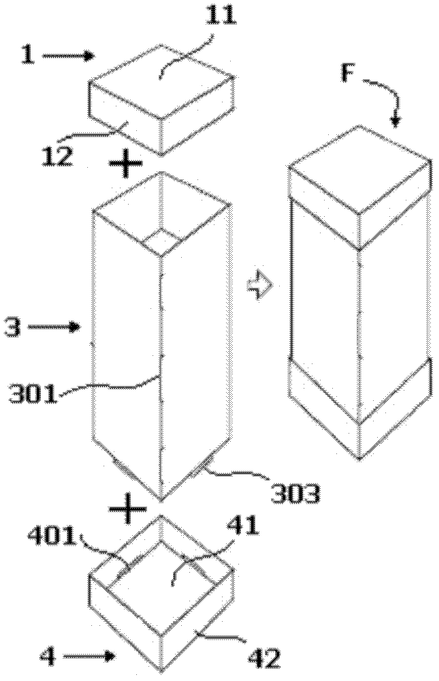
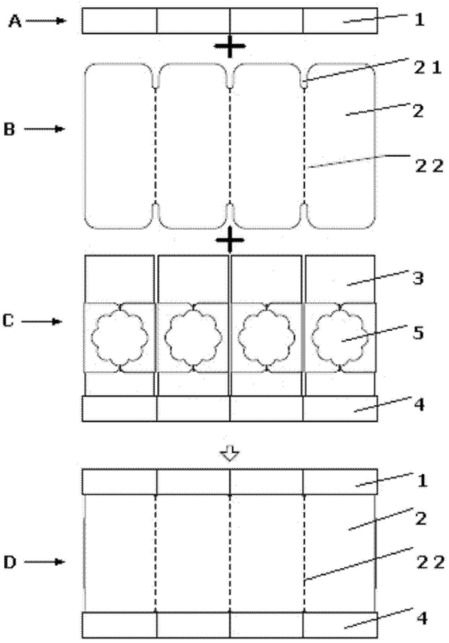
[0037] combine figure 1 , figure 1 It is a schematic diagram of the structure of the box body of the packaging box of the present invention. As shown in the figure, the packaging box includes a box body F composed of an upper box cover 1, a lower box cover 4 and a box body 3; wherein the upper box cover 1 is formed by cutting and folding a plane plate , including a bottom plate 11 and four side plates 12, and there are card slots 101 at the joints of the inner bottom plate of the box cover and the four side plates; the lower box cover 4 is formed by cutting and folding a flat plate, including a bottom plate 41 and four side plates 42. There are card slots 401 at the joints of the inner bottom plate and the four side plates of the box cover; the box body 3 is formed by cutting and folding a flat plate, and the joint of the box body after folding is connected by a card slot 301 and a card 302. At the connection between the four side walls 310 of the box body and the lower box c...


PUM


Abstract

The invention discloses a packing box which comprises a box body, connecting clamping plates and an external packing strip, wherein the box body is formed by an upper box cover, a lower box cover and a box main body, the connecting clamping plates are connected with the box body, and the external packing strip is used for conducting combined package. The packing box is a combined type packing box which is formed by a flat plate in a folding and inserted combination mode after the flat plate is pressed and cut through a cutting die. The packing box can be transported to a use place in a mode of the flat plate. In the process of the assembly of the packing box, any adhesives are not needed, and the packing box after being assembled can be arrayed and changed in a various-state mode. After the lower box cover and a clamping design at the bottom of the box main body are tightly combined, the lower box cover and the box main body are not easy to separate, and a fastening function of reinforcing the small packing box is played. Due to the fact that the connecting clamping plates are inserted and connected with the upper box cover and the lower box cover of the small packing box, connected combination package is formed, and the combination is various, free and convenient. The external packing strip not only has the decorative and beautiful functions, but also can fasten the whole package. The packing box is enabled to be combined into a complete packing article. Due to the fact that structural dislocation is considered when the packing box is designed, any adhesives are also not needed when the external packing strip is used, and simple packing and use of the packing box can be conducted.

Description

[0001] technical field [0002] The invention belongs to the technical field of packaging box design and production, in particular to the technical field of packaging box design and production that can be combined arbitrarily. Background technique [0003] Existing commonly used packaging is concentrated on synthetic boards, wooden boards, gray cardboards, metal products and other packaging materials that have been laminated and laminated. These types of packaging materials have problems such as resource waste and environmental pollution to varying degrees. The disadvantages are large volume, large storage space, high transportation cost and high production cost. [0004] Commonly used packaging boxes are manufactured at the production site and then transported to the place of use. The packaging box is bulky and the transportation cost is high. If it is made at the place of use, it is very inconvenient to make at the place of use because certain equipment and auxiliary mate...

Claims


Application Information

Patent Timeline
IPC IPC(8): B65D5/02B65D5/64B65D5/44B65D5/32B65D5/49
Inventor 黄文充
Owner 黄文充
Learn More