
Activated carbon production system

A technology of activated carbon production and feed inlet, applied in the direction of inorganic chemistry, non-metallic elements, carbon compounds, etc., can solve the problems of increased labor force, high labor intensity, and increased production costs, so as to relieve pressure, avoid dust, and avoid materials landing effect

Active Publication Date: 2016-03-23
JIANGSU PURESTAR EP TECH CO LTD
View PDF2 Cites 0 Cited by
  • Summary
  • Abstract
  • Description
  • Claims
  • Application Information

AI Technical Summary

Problems solved by technology

[0005] 1. In normal production, the post-processing of basic activated carbon needs to be done according to the needs of customers, but the post-processing in the existing production process is basically done, which causes troubles in operation
At the same time, in the follow-up processing equipment, each production link needs manual transportation to operate, resulting in an increase in labor force, increased production costs, and high labor intensity
[0006] 2. Since each production link in the follow-up processing needs manual transportation to operate, there is an unsealed material transportation, which will cause the phenomenon of materials falling and dust flying, which will affect the environment of the workshop and the mood of the staff, and will cause unnecessary waste of
[0007] 3. Due to the large number of post-processing equipment, each production link is carried out sequentially. After the processing is completed, it needs to be packaged. Otherwise, the next production cannot be carried out, which puts a lot of pressure on the warehouse, and there is still a situation where production and sales cannot be completely balanced. question
Moreover, once the converter is ignited and fed, if there are no special circumstances, it will be rotated throughout the year, which will further put more pressure on the warehouse

Method used


Image

  • Activated carbon production system

Examples


Embodiment Construction

[0022] The specific embodiments of the present invention will be described in further detail below in conjunction with the drawings and embodiments. The following examples are used to illustrate the present invention, but not to limit the scope of the present invention.

[0023] It should be noted that, for the convenience of description, the following content does not distinguish between valves with the same function, and they are collectively referred to as valves.

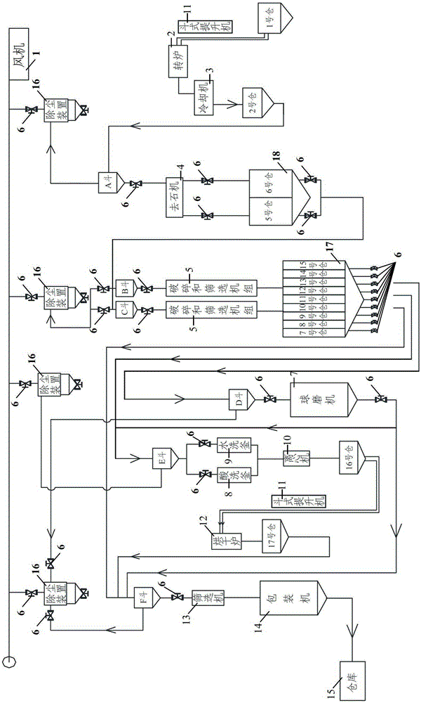
[0024] figure 1 Shown is a schematic structural diagram of an activated carbon production system in an embodiment of the present invention. Such as figure 1 As shown, the activated carbon production system in the embodiment of the present invention sequentially (here "sequential" is based on the production process of activated carbon) includes a stone remover 4, multiple sets of crushing and screening units 5, and subsequent processing The equipment, the screening machine 13 and the packaging machine 14 are connec...


PUM


Abstract

The invention belongs to the technical field of material preparation and discloses an activated carbon producing system. Pipelines are adopted to achieve sealing and communication of all equipment and avoid material dropping and dust spreading during a producing progress, and valves are arranged on all the pipelines to control transportation of materials. A plurality of first feed bins are arranged, and feeding inlets of the plurality of first feed bins are respectively communicated with different screening layers of all breaking and screening units to provide enough feed bin space to store basic activated carbon and relieve pressure of the feed bins. Feeding inlets of a ball mill, a pickling tank, a rinsing tank and a screening machine can be respectively communicated with discharging outlets of the plurality of first feed bins in a sealing and dismountable mode, and at the same time, a discharging outlet of the ball mill and the feeding inlet of the screening machine are communicated in a sealing mode through the pipelines, and corresponding subsequent treatment or directly package to finished products can be conducted according to needs of clients.

Description

Technical field [0001] The invention relates to the technical field of material preparation, in particular to an activated carbon production system. Background technique [0002] Activated carbon is an excellent adsorption material with large surface area, strong adsorption capacity, environmental protection, and non-toxicity. It is widely used in air purification, deodorization, anti-corrosion, water treatment, solution fading, chemical catalysis, chemical analysis and other fields. [0003] Combine figure 1 As shown, the production process of the existing activated carbon in the workshop is as follows: first put the raw materials such as coconut shells into warehouse 1, and the bucket elevator 11 transports the raw materials to the converter 2 for activation, carbonization, etc., and after cooling by the cooler 3 , The stone is removed by the stone removing machine 4, and then crushed and screened by the crushing and screening unit 5 to obtain basic activated carbon of different...

Claims


Application Information

Patent Timeline
Patent Type & Authority Patents(China)
IPC IPC(8): C01B31/08C01B32/39
Inventor 王洪炳
Owner JIANGSU PURESTAR EP TECH CO LTD
Learn More