Self-piercing nut

A technology for nuts and threaded holes, applied to nuts, threaded fasteners, connecting components, etc., can solve the problems of high cost, heavy load and deformation of the punching die 40, and achieve the effect of improving the life of the die

Inactive Publication Date: 2013-06-19
PIAS SALES
View PDF10 Cites 4 Cited by
  • Summary
  • Abstract
  • Description
  • Claims
  • Application Information

AI Technical Summary

Problems solved by technology

[0009] However, in recent years, especially in the automobile industry, from the viewpoint of energy saving, there is a tendency to reduce the thickness of the plate by using high-tensile steel sheets to achieve weight reduction, and even in the case of using ordinary steel, from From the viewpoint of safety improvement, there is a tendency to use thick plates with a thickness of 3.0 mm to 12.0 mm
[0010] If the above-mentioned piercing nut 31 is applied to such a high-tensile steel plate or a thick plate of ordinary steel (with a thickness of 3.0 mm to 12.0 mm), it is not only difficult to make the opening peripheral edge of the metal plate 32 punched out by the pilot part 34 The portion 33 is pressed into the annular groove 37 and the groove 36 and deformed, and the load on the protrusion 41 of the punching die 40 becomes too large, and the life of the punching die 40 is significantly reduced.
As a result, there are many problems such as the occurrence of defective products, interruption of production for mold replacement, and high cost.

Method used


Image

  • Self-piercing nut
  • Self-piercing nut
  • Self-piercing nut

Examples


Embodiment 1

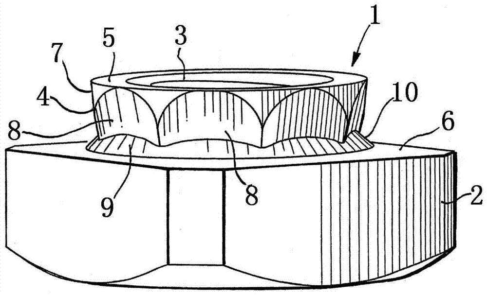
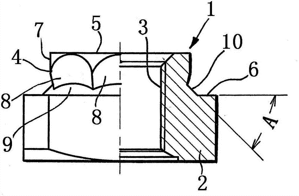
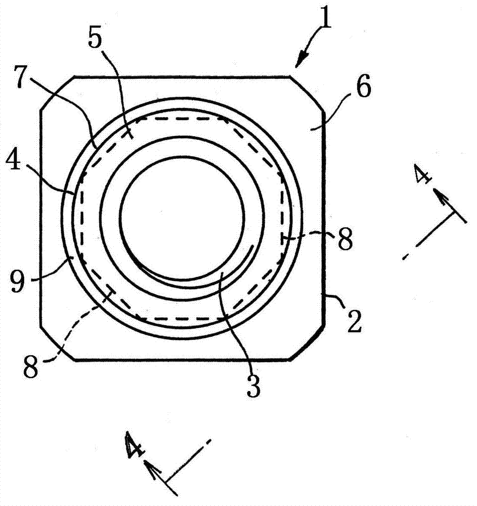
[0061] Figure 1 ~ Figure 4 Piercing nut 1 of Example 1 of the present invention is shown. The pierced nut 1 is manufactured by cold forging a common steel blank. The nut main body 2 is a rounded quadrilateral with four corners of the square nut cut off. The central part of the nut main body 2 including the threaded hole 3 protrudes. There is a cylindrical pilot part 4, and the end surface 5 of the cylindrical pilot part 4 functions as a punch for punching a metal plate. The piercing nut 1 has a fastening seat surface 6, and the fastening seat surface 6 Extends from the root of the pilot portion 4 to the outer peripheral edge of the nut main body 2 .

[0062] The peripheral edge of the end surface 5 of the pilot part 4 is formed in a circular shape, and the outer peripheral surface 7 of the pilot part 4 is composed of 6 to 12 (eight in the illustrated embodiment) flat surfaces 8 and is formed so as to gradually shrink from the end surface 5 toward the root. diameter of the p...

Embodiment 2

[0068] Such as Figure 9 ~ Figure 11 A piercing nut 15 according to Embodiment 2 of the present invention is shown. The piercing nut 15 basically has the same structure as the piercing nut 1 of the first embodiment, so the same reference numerals are assigned to the same structural parts and explanations are omitted. Next, structures different from the piercing nut 1 will be described.

[0069] Such as figure 2 As shown, the fastening seat surface 6 of the pierced nut 1 of the first embodiment is formed as a flat surface perpendicular to the axis of the nut body 2 . In contrast, as Figure 9 and Figure 11 As shown, the fastening seat surface 16 of the pierced nut 15 of the second embodiment is formed as an inclined surface that gradually becomes higher from the outer peripheral edge of the nut body 2 to the root of the pilot portion 4 . The inclination angle (B) with respect to the plane perpendicular to the axis of the nut main body 2 is preferably within a range of 5° ...


PUM


Abstract

A self-piercing nut 1 is configured in that a pilot portion 4 functions as a punch and an end face 5 punches out a metal plate 11. The pilot portion 4 is disposed in a protruding fashion at the center of a nut body 2 which includes a screw-hole 3. A fastening seat face 6 extends from the base of pilot portion 4 to the outer periphery of nut body 2, and the periphery of the end face 5 of pilot portion 4 is formed in circular shape. Outer periphery surface 7 of pilot portion 4 comprises 6 to 12 planar surfaces 8 and is also formed into a polygonal cone-like polyhedron gradually decreasing in diameter from end face 5 toward the base, and fastening seat face 6 is formed into a smooth surface without grooves or concave and convex portions. A protrusion 9 rises from fastening seat face 6 and is disposed near the base of pilot portion 4, and planar surfaces 8 are connected to protrusion 9.

Description

technical field [0001] The present invention relates to a piercing nut. The main body of the nut is equipped with a pilot portion, and the pilot portion functions as a punch for punching a metal plate. The piercing nut is riveted and fixed to the metal plate. In particular, the present invention relates to a piercing nut. A piercing nut that can be applied to a high-tensile steel plate or a thick plate of common steel. Background technique [0002] Piercing nuts have been widely used in the automobile industry and the assembly of home appliances since ancient times. However, when the piercing nut is fixedly mounted on a metal plate, it is required to have a predetermined rotation resistance and pulling resistance. In order to meet this requirement, various types of pierced nuts emerge in an endless stream. Conventional piercing nuts are generally applied to ordinary steel plates and have a structure in which the outer peripheral surface of the pilot part punched out of the ...

Claims


Application Information

Patent Timeline
Patent Type & Authority Applications(China)
IPC IPC(8): F16B37/06
CPCF16B37/068F16B37/04
Inventor 新城启氏
Owner PIAS SALES
Why Eureka
Try Eureka