Detection device and method for phase encoding synchronous time difference of ultrasonic flowmeter

A technology of phase encoding and detection device, which is applied in measurement device, measurement flow/mass flow, liquid/fluid solid measurement, etc., can solve problems such as low power consumption, achieve low power consumption, improve measurement accuracy, and avoid the effects of influence

Inactive Publication Date: 2013-06-19
NANJING UNIV OF SCI & TECH
View PDF7 Cites 7 Cited by
  • Summary
  • Abstract
  • Description
  • Claims
  • Application Information

AI Technical Summary

Problems solved by technology

The main problem to be solved is how to make the time-difference method ultrasonic flowmete

Method used


Image

  • Detection device and method for phase encoding synchronous time difference of ultrasonic flowmeter
  • Detection device and method for phase encoding synchronous time difference of ultrasonic flowmeter
  • Detection device and method for phase encoding synchronous time difference of ultrasonic flowmeter

Examples


Embodiment

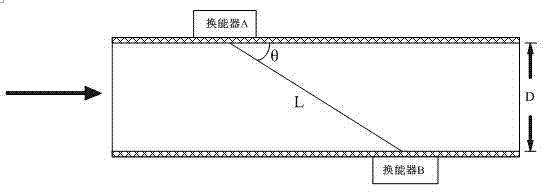
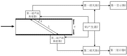
[0061] Embodiment: set the inner diameter of the fluid pipeline to be tested to be 3m, the path length of ultrasonic wave propagation to be 5m, the included angle between the direction of propagation of ultrasonic wave and the flow direction of fluid to be 36.87°, and the propagation speed of ultrasonic wave in the fluid to be 1600m / s, code The 13-bit Barker code signal sequence generated by the generator is [1 1 1 1 1-1-1 1 1-1 1-1 1], and the different delays for generating the 13-bit Barker code reference signal at the same time are 2500μs, 2501μs, 2502μs, ..., 3500 μs.

[0062] The first step: install the first ultrasonic transducer 1 and the second ultrasonic transducer 2 on both sides of the pipeline wall and stagger each other; the code generator 7 generates a 13-bit Barker code signal and a 13-bit Barker code signal Corresponding different time delays, the different time delays corresponding to the 13-bit Barker code signal are used as different reference signals, and ...


PUM


Abstract

The invention discloses a detection device and a method for phase encoding synchronous time difference of an ultrasonic flowmeter. A pair of ultrasonic transducers is used as a signal sending-receiving probe group and is respectively mounted on two sides of a pipeline with a certain distance; a measurement period of the synchronous time difference detection method comprises two processes, namely controlling the two ultrasonic transducers to be simultaneously used as a sending end to send 13-bit barker code signals of different frequencies and controlling the two ultrasonic transducers to stop sending signals and wait to receive signals, and using relevant processing methods, the time for the first ultrasonic transducer to send signals to the second ultrasonic transducer can be precisely measured and recorded, and the time for the second ultrasonic transducer to send signals to the first ultrasonic transducer can be precisely measured and recorded. According to the data, combining with geometric information, flow velocity and flow quantity can be calculated. Compared with a traditional time difference method, the detection method can meet the requirements of the time-difference method ultrasonic flowmeter on high measurement precision.

Description

technical field [0001] The invention relates to ultrasonic flowmeter technology, in particular to a phase encoding synchronous time difference detection device and method for ultrasonic flowmeters. Background technique [0002] Compared with mechanical flowmeters and electromagnetic flowmeters, ultrasonic flowmeters have many advantages: high measurement accuracy, strong adaptability to pipe diameter, non-contact measurement, convenient use and easy digital management, etc. With the development of piezoelectric ceramic technology, electronic technology and high-speed digital signal processing technology, the performance of ultrasonic flowmeter has been greatly improved, and the manufacturing cost has also been greatly reduced. Therefore, ultrasonic flowmeter has been widely used in the industrial field and daily life. widely used. [0003] At present, the time difference method is mostly used in the design of ultrasonic flowmeters for signal detection. The following is a br...

Claims


Application Information

Patent Timeline
IPC IPC(8): G01F1/66
Inventor 李洪涛朱晓华洪弘顾陈陈恒明
Owner NANJING UNIV OF SCI & TECH
Why Eureka
Try Eureka