
Testing device and measuring and calculating method for gas permeability of compact rock material

A technology for dense rock and material gas, applied in the direction of measuring devices, permeability/surface area analysis, and analyzing materials, can solve the problems of low liquid flow rate, large measurement error, and difficult test, etc., and achieve a wide range of confining pressure , simple operation and high test accuracy

Active Publication Date: 2013-06-19
HOHAI UNIV
View PDF6 Cites 56 Cited by
  • Summary
  • Abstract
  • Description
  • Claims
  • Application Information

AI Technical Summary

Problems solved by technology

[0005]For tight rock, due to the extremely low flow rate of liquid through it, it is difficult to directly measure the small flow rate through the rock sample. The measurement error is also large

Method used


Image

  • Testing device and measuring and calculating method for gas permeability of compact rock material
  • Testing device and measuring and calculating method for gas permeability of compact rock material
  • Testing device and measuring and calculating method for gas permeability of compact rock material

Examples


Embodiment 1

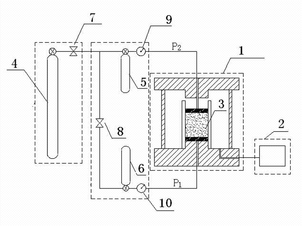
[0032] Example 1: like figure 1 As shown, a tight rock material gas permeability test device includes a pressure chamber 1, an air pressure loading system and a confining pressure loading system 2; a tight rock 3 to be tested is placed in the pressure chamber 1, and the tight rock 3 to be tested The surrounding area of ​​the compact rock 3 is loaded with confining pressure through the confining pressure loading system 2, and the two ends of the tight rock 3 to be tested are loaded with air pressure through the air pressure loading system.

[0033] The air pressure loading system includes an inert gas source 4, an upper pressure gas storage tank 5, a lower pressure gas storage tank 6 and an air pressure control device, and the inert gas gas source 4 is connected with the upper and lower pressure gas storage tanks through connecting pipelines 5, 6, conveying inert gas for the upper and lower pressure gas storage tanks 5, 6; the air pressure control device is respectively conne...

Embodiment 2

[0054] Example 2: The steps are the same as those in Example 1, except that: Step 1 selects different rock samples; Step 6 applies different pulse pressures; Step 4 applies greater confining pressure.

[0055] (1) Select Late Proterozoic granitic gneiss, process the rock sample into a cylindrical shape (see Table 3 for specific parameters), measure and record the diameter and height of the sample;

[0056] (2) Put the rock sample into the pressure chamber after being covered with high-performance rubber, and set porous metal backing plates at both ends of the rock sample, and adjust the position of the rock sample to make it balanced, so as to avoid the confining pressure not being fully effective due to uneven placement;

[0057] (3) Apply confining pressure P C When it reaches the predetermined value, close the valve of the confining pressure pump to stabilize the confining pressure at the predetermined value;

[0058] (4) Apply a small air pressure through the upper and...


PUM


Abstract

The invention discloses a testing device and a measuring and calculating method for the gas permeability of compact rock material. Under the condition that the gas pressure at two ends of a rock sample are controlled to be the same, a gas pressure pulse is applied to the lower surface of the rock sample by a gas pressure control panel. When gas penetrates through the rock sample and enters a known pressure air storage tank under the action of the pressure of the pulse, the gas permeability of the rock sample is calculated by recording the change of the pressure of the pulse with time. The testing device and the measuring and calculating method are applicable to the measurement of permeability of mediums with low permeability, such as the storage of underground petroleum and natural gas, the storage of CO2, the disposal of nuclear waste, the storage of shale gas and the like and the measurement and calculation of the permeability of other compact rock mediums. Materials the permeability of mediums is between around 10-24m2 can all be measured and calculated by the device system.

Description

technical field [0001] The invention relates to a gas permeability test device and a calculation method for tight rock materials, which are suitable for underground oil and natural gas storage, CO 2 The measurement and calculation of the permeability of low-permeability media such as storage, nuclear waste disposal and shale gas storage, and the permeability of other tight rock media. The permeability of the media is 10 -24 m 2 The left and right materials can be measured and calculated by the device system. Background technique [0002] Tight rocks are used for underground oil and gas storage, CO 2 The main medium and geological environment for storage, shale gas storage, and nuclear waste disposal are also a complex medium commonly used in engineering construction such as water conservancy and hydropower, mines, and tunnels. Due to the compact structure of tight rock, the fluid flow rate is low, and the flow rate is difficult to measure and measure, which restricts the ...

Claims


Application Information

Patent Timeline
IPC IPC(8): G01N15/08G01N7/10
Inventor 王环玲徐卫亚邵建富王欣左婧
Owner HOHAI UNIV
Learn More