
Battery module unit

A technology for battery modules and battery cells, which is applied to electrical components, battery pack components, circuits, etc., and can solve the problems of battery module length deviation, inability to fully fasten battery modules, and inability to integrate multiple battery cells , to achieve the effect of improving operability

Active Publication Date: 2013-06-19
HONDA MOTOR CO LTD
View PDF5 Cites 20 Cited by
  • Summary
  • Abstract
  • Description
  • Claims
  • Application Information

AI Technical Summary

Problems solved by technology

[0009] However, since the battery module is constituted by stacking a plurality of battery cells, there is a problem that the thickness tolerance of each battery cell accumulates and the length of the battery module varies.
Therefore, when two battery modules share a pair of end plates, if the connection member is fastened corresponding to the battery module on the longer side, the battery module on the shorter side cannot be fastened sufficiently, and there is a problem. Unable to firmly integrate multiple battery cells

Method used


Image

  • Battery module unit
  • Battery module unit
  • Battery module unit

Examples


Embodiment Construction

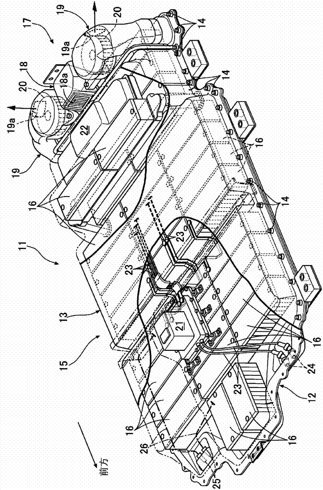
[0057] Below, based on Figure 1 to Figure 5 , the embodiment of the present invention will be described.

[0058] Such as figure 1 As shown, the battery pack 11 of an electric vehicle has a battery case 15 obtained by bonding a synthetic resin battery cover 13 to the upper surface of a metal battery tray 12 and fastening it with bolts 14 . . . A plurality of battery modules 16 . . . are mounted on the upper surface.

[0059] A cooling device 17 provided at the rear of the battery pack 11 includes a suction duct 18 disposed at the center in the vehicle width direction and a pair of left and right discharge ducts 19 disposed on both sides of the suction duct 18 in the vehicle width direction. A cooling air inlet 18 a for sucking air outside the battery pack 11 into the inlet duct 18 is opened toward the front on the upper front surface of the inlet duct 18 . In addition, electric cooling fans 20 and 20 are housed in the discharge ducts 19 and 19, respectively, and the coolin...


PUM


Abstract

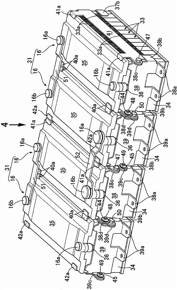
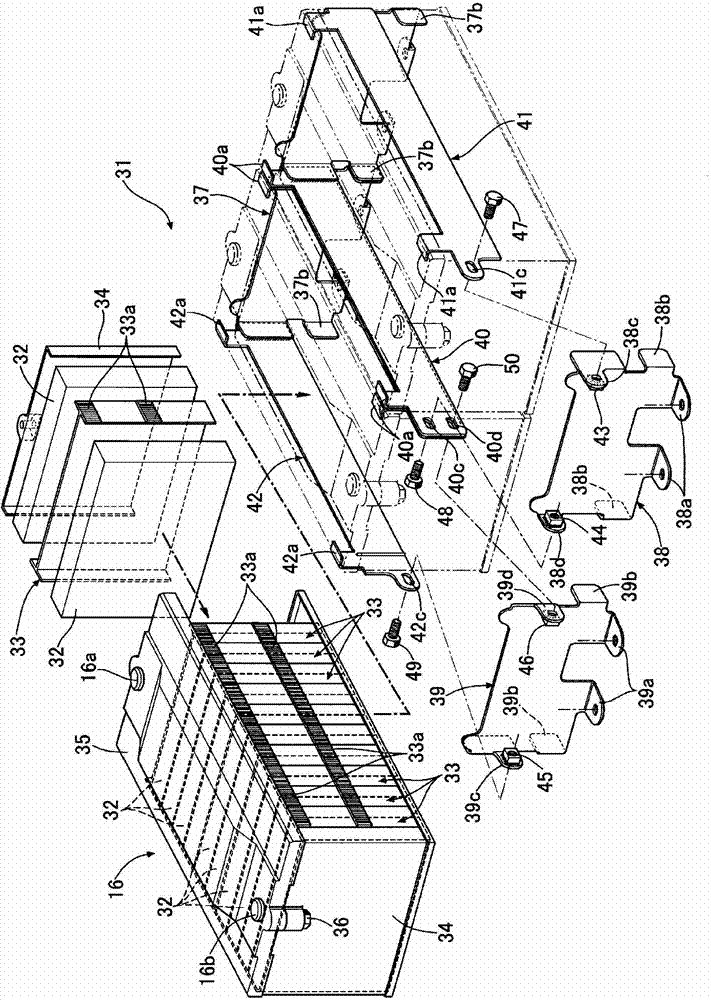
The invention provides a battery module unit, whereby a pair of battery modules are parallely arranged, and are integratedly formed, therefore the number of end plates can be reduced, and the length difference of the battery modules can be absorbed. When the pair of battery modules (16) are parallely arranged, and are integratedly formed, a first end plate (37) abuts against one end of each of the battery modules (16), and two second end plates (38,39) abut against the other ends of the battery modules (16). Compared to the battery modules (16), which are respectively provided with a pair of end plates, the number of the end plates can be reduced by one. The tolerance accumulations of tolerances of the battery bodies (32) in the length direction of the laminated two battery modules (16) can be generated, and the different positions of the two end plates (38,39) can be used to absorb the length difference.

Description

technical field [0001] The present invention relates to a battery module unit configured by arranging a pair of battery modules in parallel and integrating them. The battery module is sandwiched between a first end plate and a second end plate by stacking a plurality of battery cells. The first end plate and the second end plate are connected by a connecting member. Background technique [0002] According to the following Patent Document 1, there is known a structure in which a pair of end plates are brought into contact with both end portions of a plurality of stacked battery cells, and the pair of end plates are fastened to the restraining band (connecting member) by bolts. ) to form a battery module in which a plurality of battery cells are integrated in a laminated state. [0003] 【Prior technical literature】 [0004] 【Patent Literature】 [0005] [Patent Document 1] Japanese Patent Laid-Open No. 2009-48973 [0006] 【Summary of Invention】 [0007] 【Problems to be sol...

Claims


Application Information

Patent Timeline
Patent Type & Authority Applications(China)
IPC IPC(8): H01M2/10
CPCY02E60/10
Inventor 木村有寿山本康一安田范史藤冈征人
Owner HONDA MOTOR CO LTD
Learn More