Broadband high gain antenna with bionic form and antenna module with the same

An antenna and antenna part technology, applied in the field of communication, can solve the problems of inability to adjust the vertical and horizontal beams of radiation, low energy utilization rate, etc., to achieve the effect of improving front-to-back ratio characteristics and directionality, ensuring centralized utilization, and reducing energy radiation.

Active Publication Date: 2013-06-19
JIANGSU EAST CENTURY NETWORK INFORMATION +1
View PDF4 Cites 2 Cited by
  • Summary
  • Abstract
  • Description
  • Claims
  • Application Information

AI Technical Summary

Problems solved by technology

U.S. Patent US6259416B1 discloses an antenna combined with a slot ring structure. The antenna has relatively high gain and relatively wide frequency band characteristics. However, the antenna cannot effectively and freely control the longitudinal radiation and the transverse beam cannot be adjusted. , the energy utilization rate is low, for example, it cannot meet the requirements of modern communication technology for antennas, such as LTE antennas

Method used


Image

  • Broadband high gain antenna with bionic form and antenna module with the same
  • Broadband high gain antenna with bionic form and antenna module with the same
  • Broadband high gain antenna with bionic form and antenna module with the same

Examples


Embodiment 1

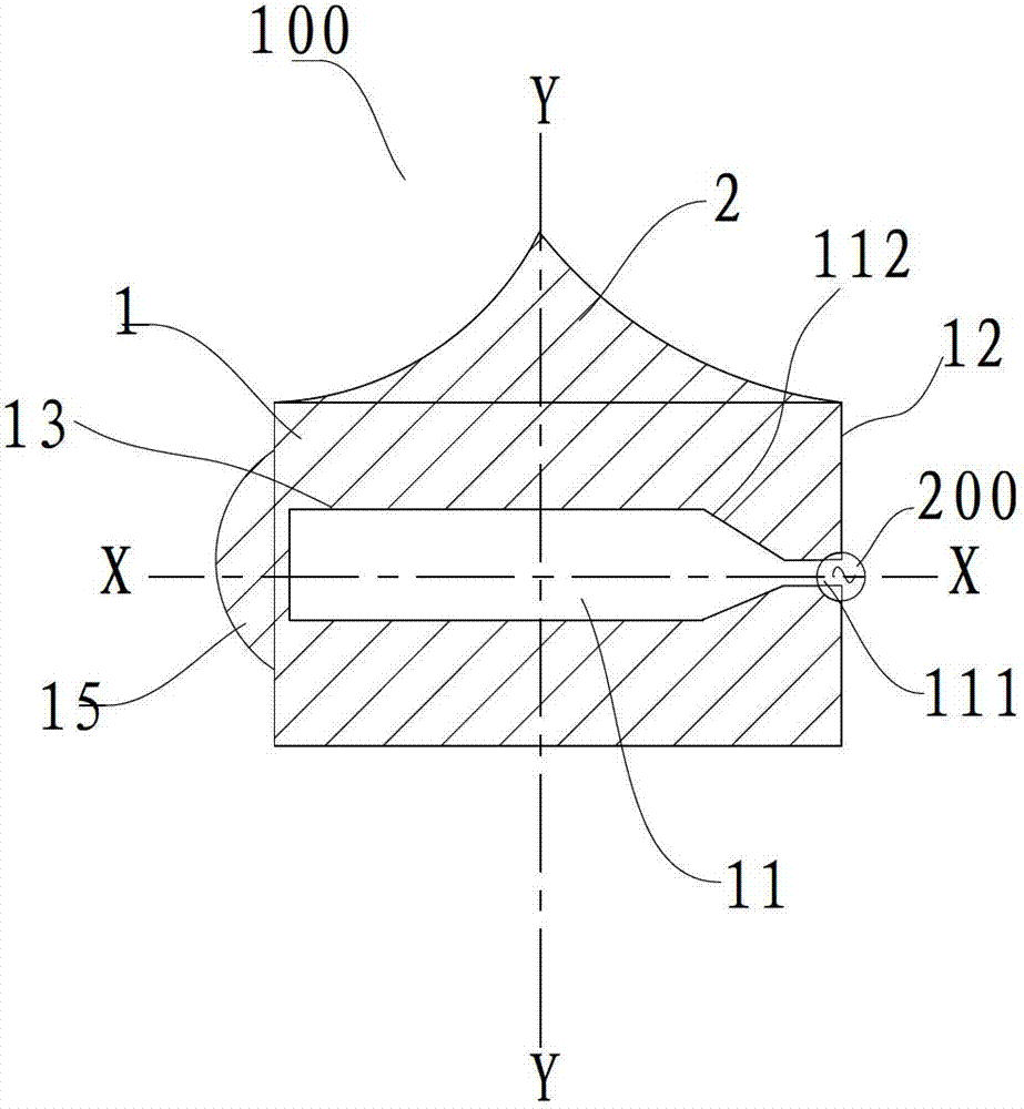
[0096] Such as figure 1 As shown, the antenna unit 100 in this embodiment includes: a first antenna component 1, a second antenna component 2 and a feeding component 200. The ring structure of the first antenna component 1 has a slot 11 formed in a rectangular shape. , And there is a tapered transition section 112 between the slot 11 and the opening 111.

[0097] The second antenna component 2 is formed into a triangle-like shape. Specifically, the long side of the second antenna component 2 is parallel and adjacent to the first antenna component 1, and the other two sides are formed as arc-shaped line segments and intersect at a tip.

Embodiment 2

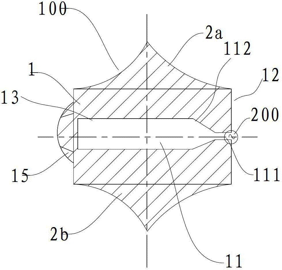
[0099] Such as figure 2 As shown, the structure of the antenna unit 100 according to this embodiment is substantially the same as that of the antenna unit 100 in the first embodiment. The only difference is that the antenna unit 100 in this embodiment includes two second antenna components 2. One 2a of the two second antenna components 2 is connected to the first side of the first antenna component 1 (such as Figure 2-Figure 6 The upper side of the two second antenna elements 2 is coupled by a direct connection, and the other 2b of the two second antenna elements 2 is connected to the second side of the first antenna element 1 opposite to the first side (such as Figure 2-Figure 6 The lower side of the middle) is coupled by a direct connection.

Embodiment 3

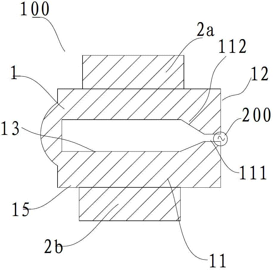
[0101] Such as image 3 As shown, the structure of the antenna unit 100 according to this embodiment is substantially the same as that of the antenna unit 100 in the second embodiment. The only difference is that the two second antenna components 2 of the antenna unit 100 in this embodiment are both formed as The rectangular shape, at this time, is formed such that the long side of the rectangle of the second antenna member 2 is parallel to and adjacent to the first (or second) side of the first antenna member 1.


PUM


Abstract

The invention discloses an antenna includes a first antenna unit and a second antenna unit. Each antenna unit of the first antenna unit and the second antenna unit includes a first antenna component and a second antenna component, the first antenna component has an annular structure is provided with a slot slit, the annular structure is provided with an outer periphery and an inner periphery limited by the line of rabbet joint, the second antenna component is coupled with the first antenna component, and the first antenna unit and the second antenna unit are arranged in a symmetrical mode. The antenna further includes a feed component which is respectively coupled with the first antenna component of the first antenna unit and the first antenna component of the second antenna unit, and the feed component is used for feeding the first antenna component of the first antenna unit and the first antenna component of the second antenna unit. According to the antenna, the facts of controllable wave beam, wide broadband and high gain can be achieved, and the concentration use of effective energy is ensured, the radiation efficiency of the antenna is greatly improved, and thus the requirements of the modern communication technology to the antenna can be met.

Description

Technical field [0001] The present invention relates to the field of communication technology, and in particular to a broadband high-gain antenna with a bionic shape and an antenna assembly with the same. Background technique [0002] With the development of modern LTE, 3G and other communication technologies, the requirements for antenna performance are getting higher and higher. For example, it requires a wide frequency band, which can cover the working frequencies of 2G, 3G and 4G at the same time, and at the same time has a higher gain and the radiation direction of the antenna. The graph also needs effective control. US Patent US6259416B1 discloses an antenna combined with a slot loop structure. The antenna has relatively high gain and relatively wide frequency band characteristics. However, the antenna cannot effectively and freely control the longitudinal radiation and the transverse beam cannot be adjusted. , The energy utilization rate is low, for example, it cannot mee...

Claims


Application Information

Patent Timeline
Patent Type & Authority Applications(China)
IPC IPC(8): H01Q1/36H01Q19/18
Inventor 漆一宏于伟谢乔治
Owner JIANGSU EAST CENTURY NETWORK INFORMATION
Why Eureka
Try Eureka