Variable power economizer used for adjusting light of street lamp
A power-variable and energy-saving technology, which is applied to light sources, electric light sources, lighting devices, etc., can solve the problems of inconvenient travel and various activities, impracticality, and increased costs, and achieves simple and fast power conversion methods and low production costs. , the effect of saving electric energy
- Summary
- Abstract
- Description
- Claims
- Application Information
AI Technical Summary
Problems solved by technology
Method used
Image
Examples
Embodiment 1
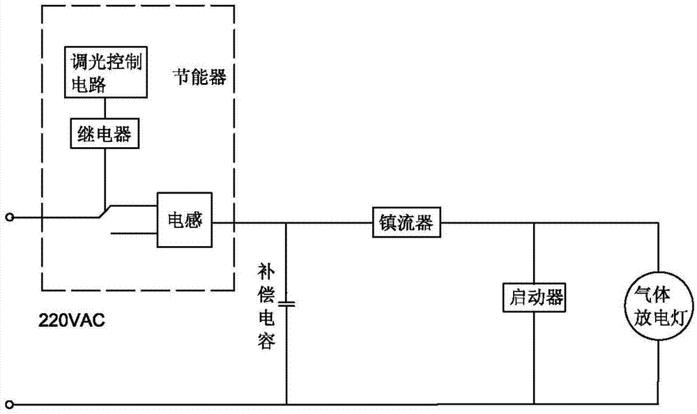
[0016] Such as figure 1 , the ballast is connected to the energy saver, the 220V power supply is connected to the dimming control circuit, ballast and lamp tube through the inductor, the ballast generates high voltage to break down the lamp tube to start the street lamp, the dimming control circuit is connected to the relay, and the relay is connected to the inductor , the dimming circuit includes a microcontroller, a memory, and peripheral circuits, etc. The microcontroller can set a variety of delayed dimming modes. In this embodiment, four delayed dimming modes are set:
[0017] Mode 1, turn on the light at 18:00 every day, delay 5 hours to reduce to half power operation, and reduce to 0 power after 11 hours of lighting (that is, turn off the light).
[0018] Mode 2, turn on the light at 19:00 every day, delay 4 hours to reduce to half power operation, and reduce to 0 power after 9 hours of lighting (that is, turn off the light).
[0019] Mode 3, turn on the light at 18:00...
Embodiment 2
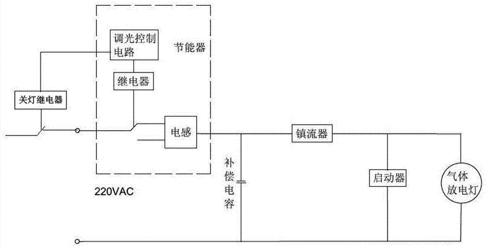
[0023] Compared with Embodiment 1, this embodiment adds a light-off relay, mainly because when the mode conversion is required, the street light can be turned off by the light-off relay (because the sky is already bright at this time) when it is time to turn off the light normally. However, the power supply of the circuit is not turned off, and the circuit continues to be energized, so that the power-on time recorded by the microprocessor exceeds the preset switching time, thereby changing the dimming mode. Both the dimming mode and the dimming method are the same as those in Embodiment 1.
Embodiment 3
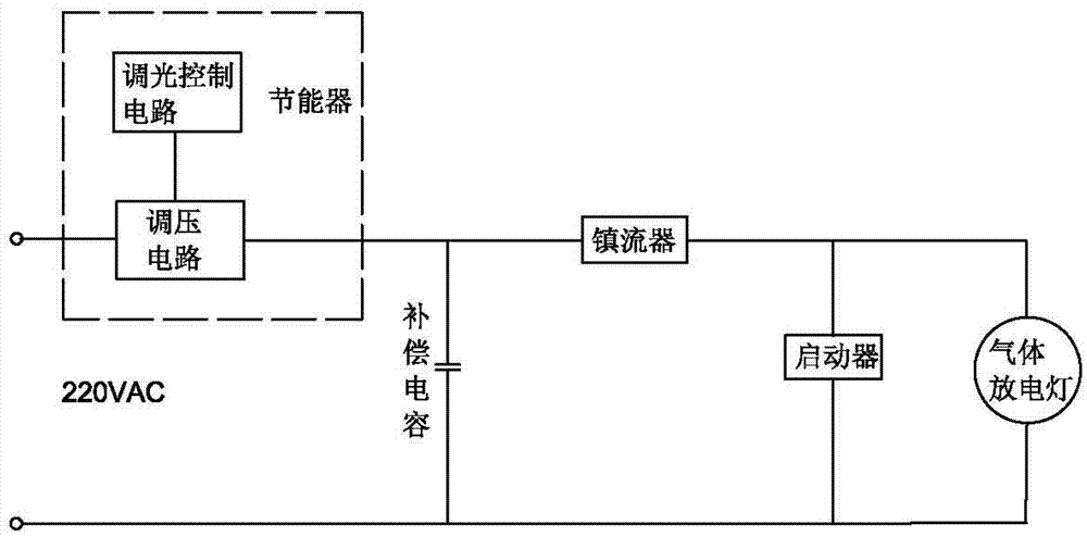
[0025] The difference between this embodiment and Embodiment 1 is that the voltage regulation circuit is controlled by the dimming control circuit, and the voltage connected to the ballast is adjusted to change the output power of the ballast: at the same time, the dimming mode set is also the same as Different from Embodiment 1, this embodiment sets four delay dimming modes:
[0026] Mode 1, turn on the light at 18:00 every day, delay 3 hours to reduce to 90% power operation of full power, delay 5 hours to reduce to half power operation, and reduce to 0 power after 11 hours of lighting (that is, turn off the light).
[0027] Mode 2, turn on the light at 19:00 every day, delay 2 hours to reduce to 90% power operation of full power, delay 4 hours to reduce to half power operation, and reduce to 0 power after 9 hours of lighting (that is, turn off the light).
[0028] Mode 3, turn on the light at 18:00 every day, delay 3 hours to reduce to 90% power operation of full power, dela...
PUM
 Abstract
Description
Claims
Application Information
 - R&D
- Intellectual Property
- Life Sciences
- Materials
- Tech Scout
- Unparalleled Data Quality
- Higher Quality Content
- 60% Fewer Hallucinations
Browse by: Latest US Patents, China's latest patents, Technical Efficacy Thesaurus, Application Domain, Technology Topic, Popular Technical Reports.
© 2025 PatSnap. All rights reserved.Legal|Privacy policy|Modern Slavery Act Transparency Statement|Sitemap|About US| Contact US: help@patsnap.com


